4-Port Mini-SAS Backplane 80H103215-013 ver. A2~A3.1 User’s Manual CHENBRO Storage Chassis 4-Port Mini-SAS Backplane 80H103215-013 Version A2~A3.1 May / 28 / 2008 15Fl., No.150, Jian Yi Road, Chung Ho City, Taipei Hsien, Taiwan R.O.C., Tel: +886 2 82265500 Fax: +886 2 82265392 Email: info@chenbro.com.tw 1 w w w . c h e n b r o .
4-Port Mini-SAS Backplane 80H103215-013 ver. A2~A3.1 User’s Manual Copyright Copyright © 2006 Chenbro Micom Co., Ltd.. All rights reserved. Unless otherwise indicated, all materials in this manual are copyrighted by Chenbro Micom Co., Ltd.. All rights reserved. No part of this manual, either text or image may be used for any purpose other than internal use within purchasing company.
4-Port Mini-SAS Backplane 80H103215-013 ver. A2~A3.1 User’s Manual Contents Copyright......................................................................................................................................................2 Technical Support......................................................................................................................................2 Contents ................................................................................................................
-Port Mini-SAS Backplane 80H103215-013 ver. A2~A3.1 User’s Manual Revision History Date May / 28 / 2008 Modifications z First release w w w . c h e n b r o . c o m 15Fl., No.150, Jian Yi Road, Chung Ho City, Taipei Hsien, Taiwan R.O.C., Tel: +886 2 82265500 Fax: +886 2 82265392 Email: info@chenbro.com.
4-Port Mini-SAS Backplane 80H103215-013 ver. A2~A3.1 User’s Manual Backplane Specification Host Interface Mini-SAS (SFF-8087) HDD Interface SAS (22+7) and SATA-II compatible Hot-Swap Yes, allows user to replace HDD on line LED indicates HDD status (Defined by Chenbro) Power LED – Blue ( When HDD is present ) Display Access LED –Green (When HDD is busy ) Error indicator – Red (Error when retreating signals ) Cooling Five Fan connectors Environment Monitor Temperature sensor 1.
4-Port Mini-SAS Backplane 80H103215-013 ver. A2~A3.
4-Port Mini-SAS Backplane 80H103215-013 ver. A2~A3.
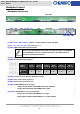
4-Port Mini-SAS Backplane 80H103215-013 ver. A2~A3.1 User’s Manual Backplane Assembly The Chenbro 4-Port Mini-SAS Backplane can be assembled on Chenbro Storage Server Chassis only. Please refer to the Chassis Quick Installation Guide for detail information. Figure 1: Front and Rear View of 3U Backplane assembly set (Using two 2U Backplane assembly sets) 15Fl., No.150, Jian Yi Road, Chung Ho City, Taipei Hsien, Taiwan R.O.C., Tel: +886 2 82265500 Fax: +886 2 82265392 Email: info@chenbro.com.
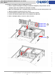
4-Port Mini-SAS Backplane 80H103215-013 ver. A2~A3.1 User’s Manual (A) Example of assembly procedure for RM31212B chassis 1. Get the complete 3U backplane assembly set (with three backplanes) ready and make sure the backplane guide rail is installed before backplane assembly. 2. Make sure the backplane ID is configured properly from bottom to top with starting from #1 to #3. 3. Slide the backplane assembly set into the chassis. 4. Fix the backplane assembly set with screws on both sides of chassis. 5.
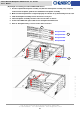
4-Port Mini-SAS Backplane 80H103215-013 ver. A2~A3.1 User’s Manual (B) Example of assembly procedure in RM41416B chassis 1. Get the complete 4U backplane assembly set (with two 2U backplane assembly sets) ready and make sure the backplane guide rail is installed before backplane assembly. 2. Make sure the backplane ID is configured properly from bottom to top with starting from #1 to #4. 3. Slide the backplane assembly set into the chassis one by one. 4.
4-Port Mini-SAS Backplane 80H103215-013 ver. A2~A3.1 User’s Manual LED Board Specification According to HDD sequential spin up setting, please refer to the following instruction. The text printing of HDD sequential spin up function setting on older version 1U~5U LED boards are incorrect. The incorrect LED board version are: 80H033117-002 ver. A0~A2 (1U) 80H033215-005 ver. A0~A2 (2U~4U) 80H173519-003 ver. A0~A1 (5U) The corrected LED board version are: 80H033117-002 ver. A3 (1U) 80H033215-005 ver.
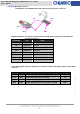
4-Port Mini-SAS Backplane 80H103215-013 ver. A2~A3.1 User’s Manual 2U~4U LED Board (Part Number 80H033215-005) I2C connector Signal connector to backplane System signal connector to M/B Function Switch USB 2.0 connector to M/B Power supply alarm mute connector (Yellow & Black Cable from PSU) Power supply alarm signal connector (Red & Black Cable from PSU) HDD Activity LEDs USB 2.
4-Port Mini-SAS Backplane 80H103215-013 ver. A2~A3.1 User’s Manual 5U LED Board and Display Board I2C connector LED Board (Part Number 80H173519-003) System signal connector to M/B USB 2.0 connector to M/B Signal connector to backplane Function Switch Power supply alarm mute connector (Yellow & Black Cable from PSU) Power supply alarm signal connector (Red & Black Cable from PSU) Signal connector to display board Power Switch USB 2.
4-Port Mini-SAS Backplane 80H103215-013 ver. A2~A3.1 User’s Manual Power Supply Alarm Mute Connector Definition Pin 1: Ground Pin 2: Alarm mute signal output to PSU (Active low) Pin 2 Pin 1 Power Supply Alarm Signal Connector Definition Pin 1: Ground Pin 2 Pin 2: PSU fail signal (TTL) input from PSU (Active low) Pin 1 Only redundant PSU come with the failure alarm and alarm mute reset control via signal connector. Make sure the redundant PSU that user applied come with the connectors above.
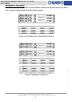
4-Port Mini-SAS Backplane 80H103215-013 ver. A2~A3.1 User’s Manual Mini-SAS Cables The Mini-SAS backplane provides most benefits to users using the same backplane to support various SAS/SATA HBA or RAID card via different conversion cables. Chenbro provides various cables for different interfaces which include the followings: (D) (B/G) (E) (C1) (F) 15Fl., No.150, Jian Yi Road, Chung Ho City, Taipei Hsien, Taiwan R.O.C., Tel: +886 2 82265500 Fax: +886 2 82265392 Email: info@chenbro.com.tw 15 w w w .
4-Port Mini-SAS Backplane 80H103215-013 ver. A2~A3.
4-Port Mini-SAS Backplane 80H103215-013 ver. A2~A3.1 User’s Manual Backplane and LED Board Wiring 1. LED board signal cable: Get the HDD activity signals and internal protocol for the spin up of each backplane. This cable connects the backplanes (start from #1) and LED board. 2. Discrete HDD failure signal cable: This cable is optional for the HBA or RAID card with HDD failure signal support. It is connected by direct cable connection, and each backplane needs one 4P-4P discrete cable. 3.
4-Port Mini-SAS Backplane 80H103215-013 ver. A2~A3.1 User’s Manual Example for RM21508B chassis Mini-SAS backplane wiring Mini-SAS cable LED board signal cable LED Board HBA / RAID Card Chassis fan wiring (Connecting start from Fan1) CN4 jumper set on pins 3 & 4 HDD8 HDD7 HDD6 HDD5 CN4 jumper set on pins 1 & 2 HDD4 HDD3 HDD2 HDD1 Chassis Fan x4 w w w . c h e n b r o . c o m 15Fl., No.150, Jian Yi Road, Chung Ho City, Taipei Hsien, Taiwan R.O.C.
4-Port Mini-SAS Backplane 80H103215-013 ver. A2~A3.1 User’s Manual Example for RM31212B Mini-SAS backplane wiring Mini-SAS cable LED board signal cable LED Board Chassis fan wiring HBA/RAID Card (Connecting start from Fan1) CN4 jumper set on pins 5 & 6 HDD12 HDD11 HDD10 HDD9 CN4 jumper set on pins 3 & 4 HDD8 HDD7 HDD6 HDD5 CN4 jumper set on pins 1 & 2 HDD4 HDD3 HDD2 HDD1 Chassis Fan x4 w w w . c h e n b r o . c o m 15Fl., No.150, Jian Yi Road, Chung Ho City, Taipei Hsien, Taiwan R.O.C.
4-Port Mini-SAS Backplane 80H103215-013 ver. A2~A3.1 User’s Manual Example for RM41416B Mini-SAS backplane wiring Mini-SAS cable LED board signal cable LED Board HBA/RAID Card Chassis fan wiring (Connecting start from Fan1) HDD16 HDD15 HDD12 HDD11 HDD8 HDD4 HDD7 HDD3 HDD14 HDD13 HDD10 HDD9 HDD6 HDD5 HDD2 HDD1 Chassis Fan x5 w w w . c h e n b r o . c o m 15Fl., No.150, Jian Yi Road, Chung Ho City, Taipei Hsien, Taiwan R.O.C.
4-Port Mini-SAS Backplane 80H103215-013 ver. A2~A3.