
Manual


Chenbro Storage Chassis
16-Port 6Gbps Mini-SAS Expander Backplane User’s Manual
http://www.chenbro.com
7
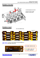
Rear View ( Host Connectors IN )
[CSIN] [COUT]: Mini-SAS Connector
[FAN1 / FAN2 / FAN3 / FAN4] : 4-pin Fan connectors
[JP1~JP5] : Standard 4-pin Power connectors (+5V and +12V)
[PC1] : 4-pin Power connector for Optical Drive
[PC2] : 4-pin Power connector for FDD
[JC1] : UART_232 Connector for firmware update
[JC4] : 2pin Power supply fail alarm connector, and shall connect to LED board
[JC5] : 2pin Power supply fail mute connector, and shall connect to LED board
[JC6] : The system status LED and mute function pin, and it is connect to LED board
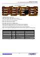
[SW1] : Function Switch, the following table shows the functions which is related to the setting of SW1
Function DIP NO. ON OFF
Fan Monitor DIP1 Enable Monitor 4pcs fan status Enable Monitor 3pcs fan status
PWN Control option DIP2 Enable BP control PWM fan Disable BP control PWM fan
Temp Setting DIP3
Set 65℃ as alert temp Set 55℃ as alert temp
Temp Alert DIP4 Enable over temp alarm Disable over temp alarm
Buzzer DIP5 Enable buzzer alarm Disable buzzer alarm
SES uplink to RAID Card DIP6 Enable SES uplink Disable SES uplink
JP5
PC1
JP4
COUT
CSIN
Fan1 Fan2
F
an3
Fan4
JP3
JP2
JP1
SW1
JC5
JC4
JC6
JC1
PC2
JF5
LED3
LED2