
Owner manual

12-Port 6Gb/s Mini-SAS Backplane 80H10323602A1
User’s Manual
15Fl., No.150, Jian Yi Road, Chung Ho City, Taipei Hsien, Taiwan R.O.C.,
Tel: +886 2 82265500 Fax: +886 2 82265392 e-mail: info@chenbro.com.tw
7
w w w . c h e n b r o . c o m
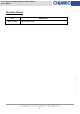
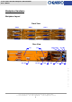
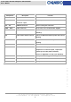
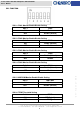
Components Description Function
CN011 ~ CN121 29 pin SAS Connector – to HDD
For SAS/SATA HDD connection
CB1 ~ CB3 Mini-SAS SFF-8087
Connector – Input
Internal input from SAS RAID Card or M/B
JF1 ~ JF4 PWM fan Connector Chassis cooling fan connection
CN01 ~ CN04 Power Connector DC in, 4-Pin, +5V/+12V from Power Supplier
SW1 DIP Switch The function is for fan control enable and disable
switching.
JP1 Power Failure Alarm Connector
Connect to Redundant PSU for power failure alarm
signaling
JM1 Power Failure Mute Connector Connect to Redundant PSU for power failure mute
signaling
CN05 LED board connector Signal connection to chassis LED board
CN06 M/B PWM fan Connector Gets either PWM duty cycle of M/B or B/P for
comparison to control fan speed , required one
optional special cable (26H11313601A0)
(Please see Appendix 1 for duty cycle definition)
JA3/JA4 Multi ICE pin connector Factory reserved for upgrade & debug
JP2/JP3 IIC Connector Factory reserved
JT1/JT2 Test Connector Factory reserved for thermal contact