6-Port 3Gb/s Mini-SAS Backplane 80H10321709A0 User’s Manual CHENBRO 6-Port 3Gb/s Mini-SAS Backplane 80H10321709A0 August / 2010 15Fl., No.150, Jian Yi Road, Chung Ho City, Taipei Hsien, Taiwan R.O.C., Tel: +886 2 82265500 Fax: +886 2 82265392 Email: info@chenbro.com.tw 1 w w w . c h e n b r o .
6-Port 3Gb/s Mini-SAS Backplane 80H10321709A0 User’s Manual Copyright Copyright © 2010 Chenbro Micom Co., Ltd.. All rights reserved. Unless otherwise indicated, all materials in this manual are copyrighted by Chenbro Micom Co., Ltd.. All rights reserved. No part of this manual, either text or image may be used for any purpose other than internal use within purchasing company.
6-Port 3Gb/s Mini-SAS Backplane 80H10321709A0 User’s Manual Contents Copyright ................................................................................................................................................. 2 Technical Support .................................................................................................................................... 2 Contents ..........................................................................................................................
6-Port 3Gb/s Mini-SAS Backplane 80H10321709A0 User’s Manual Safety Instruction CAUTION: Informs the user of conditions that might result in damage to hardware, corruption of customer data or application software, or long-term health hazard to people. A caution always precedes the information to which it relates. WARNING: Alerts the user to conditions that might result in injury or death. A warning always precedes the information to which it pertains.
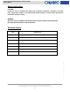
6-Port 3Gb/s Mini-SAS Backplane 80H10321709A0 User’s Manual 3Gb/s Backplane Specification P/N: 80H10321709A0 2 x Mini-SAS interface (SFF-8087) for host side (w/lock housing), port Host Interface distribution should be “4+2” HDD Interface SAS (15+7+7) and SATA-II (15+7)compatible with 3.
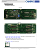
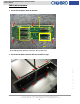
-Port 3Gb/s Mini-SAS Backplane 80H10321709A0 User’s Manual Backplane Layout Backplane Connectors Front View Rear View (2) [LD012 / LD022 / LD032 / LD042 / LD052 / LD062] : “Green lights flash” indicated hard drive is working. “Red lights on” indicated hard drive abnormal or malfunction. (3) [JF1 / JF2 / JF3 / JF4] : Fan connector (3pin) 15Fl., No.150, Jian Yi Road, Chung Ho City, Taipei Hsien, Taiwan R.O.C., Tel: +886 2 82265500 Fax: +886 2 82265392 Email: info@chenbro.com.tw 6 w w w .
6-Port 3Gb/s Mini-SAS Backplane 80H10321709A0 User’s Manual (4) [CN01 / CN02] : Power connector (+5V and +12V 4pin) (5) [J15] : Alarm mute connector (To redundant power supply) (6) [J14] : Power supply abnormal alarm connector (From redundant power supply) (7) [CN3 / CN6 / J1] : Reserved for Chenbro use only. Pin Number Monitor On 1 Fan1 Enable Disable 2 Fan2 Enable Disable 3 Fan3 Enable Disable 4 Fan4 Enable Disable 5 TEMP 65 degC Off 55 degC 15Fl., No.
6-Port 3Gb/s Mini-SAS Backplane 80H10321709A0 User’s Manual (9) [SW2] : SGPIO function switch.
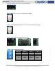
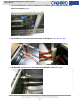
6-Port 3Gb/s Mini-SAS Backplane 80H10321709A0 User’s Manual Fabricate sequence 1. Screw the backplane with the bracket. CN1 CN2 Note: HDD grouping definition responds to above yellow mark 2. Screw the backplane bracket with the hard drive cage. w w w . c h e n b r o . c o m 15Fl., No.150, Jian Yi Road, Chung Ho City, Taipei Hsien, Taiwan R.O.C., Tel: +886 2 82265500 Fax: +886 2 82265392 Email: info@chenbro.com.
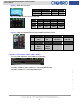
6-Port 3Gb/s Mini-SAS Backplane 80H10321709A0 User’s Manual 3. The front LED board is connected with the fan fail LED & power temp LED & global mute switch to backplane. [JF12] 4. The middle fans are connected to the header on backplane. [ JF1 / JF2 /JF3 / JF4] 5. The MiniSAS connector are connected with the MiniSAS cable. [CN1 / CN2] w w w . c h e n b r o . c o m 15Fl., No.150, Jian Yi Road, Chung Ho City, Taipei Hsien, Taiwan R.O.C., Tel: +886 2 82265500 Fax: +886 2 82265392 Email: info@chenbro.com.