
User guide

LED Board 80H03324101A0
User’s Manual
15Fl., No.150, Jian Yi Road, Chung Ho City, Taipei Hsien, Taiwan R.O.C.,
Tel: +886 2 82265500 Fax: +886 2 82265392 Email: info@chenbro.com.tw
6
w w w . c h e n b r o . c o m
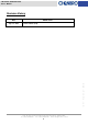
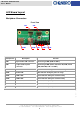
LED Board Layout
Backplane Connectors
Components
Description Function
CN1 9 pin header USB connector Connecting to M/B (USB1 & USB 2)
CN1 13 pin header System
connector
Connecting to M/B (Power SW, Reset SW, GND, Power
LED, HDD LED, LAN 1 & LAN 2)
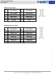
LED1 HDD LED Yellow indicator during the HDD access stage
LED2 Power LED Blue indicator during the power on stage
LED3 LAN 1 LED Green indicator during the network activity
LED4 LAN 2 LED Green indicator during the network activity
PB1 Power Switch Push button for system power on
PB1 Reset Switch Push button for system reset
PB2 Power Switch Push button for system power on
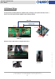
Front View
CN2
USB2 PB1 LED1~4
USB1
CN1
PB2