LED Board 80H03324101A0 User’s Manual CHENBRO LED Board 80H03324101A0 User’s Manual Sep / 15 / 2012 15Fl., No.150, Jian Yi Road, Chung Ho City, Taipei Hsien, Taiwan R.O.C., Tel: +886 2 82265500 Fax: +886 2 82265392 Email: info@chenbro.com.tw 1 w w w . c h e n b r o . c o m Ver. 1.
LED Board 80H03324101A0 User’s Manual Copyright Copyright © 2012 Chenbro Micom Co., Ltd.. All rights reserved. Unless otherwise indicated, all materials in this manual are copyrighted by Chenbro Micom Co., Ltd.. All rights reserved. No part of this manual, either text or image may be used for any purpose other than internal use within purchasing company.
LED Board 80H03324101A0 User’s Manual Contents Technical Support Copyright Revision History LED Board Specification LED Board Hardware Layout LED Board Wiring w w w . c h e n b r o . c o m 15Fl., No.150, Jian Yi Road, Chung Ho City, Taipei Hsien, Taiwan R.O.C., Tel: +886 2 82265500 Fax: +886 2 82265392 Email: info@chenbro.com.
LED Board 80H03324101A0 User’s Manual Revision History Date Sep / 15 / 2012 Modifications First release (V1.0) w w w . c h e n b r o . c o m 15Fl., No.150, Jian Yi Road, Chung Ho City, Taipei Hsien, Taiwan R.O.C., Tel: +886 2 82265500 Fax: +886 2 82265392 Email: info@chenbro.com.
LED Board 80H03324101A0 User’s Manual LED Board Specification P/N : 80H03324101A0 (Version A0) Specification Display LED indicates status HDD LED – Yellow (When HDD is busy) Power LED – Blue (When power on) LAN1、LAN2 LED – Green (When internet is busy) Connectors 1. Pin header 2.0mm (2x7) *1 2. Pin header 2.54mm (2x5) *1 Dimension 82 (L) x 30 (W) x 1.
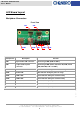
LED Board 80H03324101A0 User’s Manual LED Board Layout Backplane Connectors Front View CN1 USB2 Components CN2 USB1 PB1 Description LED1~4 PB2 Function 9 pin header USB connector Connecting to M/B (USB1 & USB 2) CN1 13 pin header System Connecting to M/B (Power SW, Reset SW, GND, Power connector LED, HDD LED, LAN 1 & LAN 2) LED1 HDD LED Yellow indicator during the HDD access stage LED2 Power LED Blue indicator during the power on stage LED3 LAN 1 LED Green indicator during the netwo
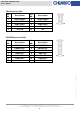
LED Board 80H03324101A0 User’s Manual USB Connector (CN1) Pin NO. Descriptions Pin NO. Descriptions 1 USB1 POWER 2 USB2 POWER 3 USB1 DATA - 4 USB2 DATA - 5 USB1 DATA + 6 USB2 DATA + 7 USB1 GND 8 USB2 GND 9 KEY PIN 10 NC SYSTEM Connector (CN2) Pin NO. Descriptions Pin NO.
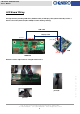
LED Board 80H03324101A0 User’s Manual LED Board Wiring Through Chenbro providing USB cable (26H033219-001) and Display cable (26H11324101A0) to make 3 boards connection (LED board, B/P & M/B) as below drawing showing. USB cable Display cable photo #a photo #b M/B photo #c LED Board Remarks: P/N are subjected to be changed without notice photo #b photo #c 15Fl., No.150, Jian Yi Road, Chung Ho City, Taipei Hsien, Taiwan R.O.C., Tel: +886 2 82265500 Fax: +886 2 82265392 Email: info@chenbro.com.