
Installation Guide Part 3


NGL FX Installation Manual Rev. *
77 of 84
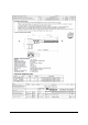
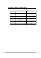
Antenna Type Jumper Settings
PX J7, J11
QX J7, J11
Table 10: Coupler Board Jumper Settings
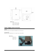
4. Check the cable connection including the RG59 coax and the LED/Sounder cable. Make
sure all cable connection is solid. For the LED/Sounder cable, make sure the ferrite choke
is in place.
5. If there is still resonance, then check the binocular cores, which can cause resonance
problem due to magnetization. Generally the ferrite magnetization issue can be solved by
degaussing. However, in some cases, the ferrites can be irreversibly damaged and have to
be replaced.
6. On the coupler board, ensure that the jumper for J14 of the O-loop is in place for
grounding.
7. The above steps address the resonance problem caused by the system itself. If there is an
environmental resonance, then follow the standard tuning procedure used for regular
Evolve/Liberty systems to alleviate the resonance problem. One common practice is to
change the TX/RX settings. The only difference is that for the Coupler system, the 2-loop
and 3-loop are combined together and cannot be individually tuned in terms of TX/RX.
Jammer Indication
Recently our customers have become concerned about different confiscated jammer devices
blinding our systems by reducing detection and allowing tagged merchandise to become
undetectable. For this reason a jammer indication feature was created to allow the customer to
track these devices. The Jammer Indication feature is enabled when the Jammer Threshold switch
is set to anything other then 0. One of the limitations with the feature is false indications when a
sweeper is in close proximally. This is obvious when enabling this feature. If this is the case, the
feature can not be used. In a clean environment the Jammer Threshold for both PAB and SAB is
set for 11.
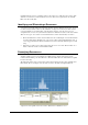
Data Retrieval
Event History
The only way to retrieve data from a TR4215 board is to connect to the Badge Board port (RS-232)
using the DMS tool. Using DMS display the Event History and (optionally) save the event history
to a .csv file. The file will be saved in a CSV format in the host computer.
For detailed information about using the DMS tool to access the Event History, please refer to
Field Service Diagnostic Management User Manual.
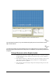
Snap Shot feature
For detailed information about using the DMS tool to access the Event History and obtain a
snapshot view of the selected alarm (from the last 10 alarm events), please refer to Field Service
Diagnostic Management User Manual.