
Installation Guide Part 3


NGL FX Installation Manual Rev. *
76 of 84
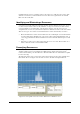
Figure 46: Acceptable low level resonance, Filter View 'C'
Note1:
If the environmental resonances (if any) can be identified and physically removed, then the RX Gain can be set
higher for better detection.
Note2:
The TR4215 board exhibits some natural internal resonance around 8 MHz which does not need to be tuned out.
Because the signal is internal and the fact the Analog View is now multiplied by 2, the typical tuning should look like
the figure 46.
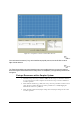
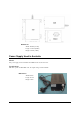
Fixing a Resonance with a Coupler System
1. Check the 2-loop and 3-loop connection. Make sure the 2-loop is connected to J2 and 3-
loop is connected to J3 of the coupler board. An incorrect loop connection will cause a
resonance problem.
2. Then check the antenna loop polarity. The 2-loop and 3-loop should be connected out of
phase. Incorrect polarity will cause resonance problem. If so, normally flipping the
antenna leads of the 3-loop will fix it.
3. Next, check the coupler board jumper settings. Incorrect jumper settings can also cause
resonance problem.