
Installation Guide Part 3

NGL FX Installation Manual Rev. *
69 of 84
Smart Alarm Management (SAM) Submenu
The TR4215 board supports the basic options, but of course only supports the limited feature set
for provide by this board. For information about SAM please refer to section on Configuring SAM
in Chapter 6.
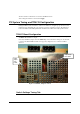
LED Definitions
System Status Indicators (DS1-DS3, DS9-DS12)
DS1 (Green) - DSP Sync
Heart beat. Indicates the firmware is running correctly when green.
DS2 (Green) - Inter-pedestal Transmit Enabled
This LED indicates the system is transmitting serial data on the inter-pedestal network, which is
not used for the TR4215.
DS3 (Green) and DS9 (Yellow)
See Sync Indicators below.
DS9 (Yellow) - Inter-pedestal Receive Data is Present in FPGA FIFO
Excess data communication is present. System might be slow. This LED is not used for the
TR4215.
DS10 (Red) - FPGA Interrupt Pending
When this LED is lit, an interrupt has been issued by the FPGA indicating either Inter-pedestal or
IDC data is present. The LED will turn off when the interrupt is handled by the Blackfin. This is
popularly known as the ‘Red LED of death’ as the board is non-recoverable in the field; only an
experienced technician might recover the board.
DS11 (Red) - FPGA Load
This red LED indicates the program status of the FPGA device. When this is lit, the FPGA is
being programmed. After the programming is complete, the LED should be off.
DS12 (Green) - Writing to Flash File System
This LED is lit when the system is writing data to the flash file system. This is a good indication
when a flash write is completed.
Internal/External Sync Indicators (DS1, DS9)
This applies to Phase 2 and above.
External loss of sync indication could be setup in SAM allowing the user flexibility in setting up a
unique indication.