
Installation Guide Part 3

NGL FX Installation Manual Rev. *
68 of 84
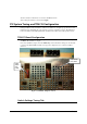
• Port Checkbox – When checked this port is enabled. Unchecked disables the port for
both transmit and receive.
• AGC Checkbox – At this point this feature is not used and a manual adjustment of the
RX hardware gain must be done via the soft LED (Saturation Indicator) for noisy
conditions. In the future when a certain threshold is detected, just before hardware
saturation, an automatic RX hardware gain adjustment will occur allowing a dynamic
reaction to a noisy condition. More information will be given later in this document about
tuning to eliminate hardware saturation.
Antenna Type
There is only one antenna type for the TR4215 board is the PAB-SAB type. Detector or
deactivator modes are not supported at this time.
Friendly Name
This is a textbox allowing the user to give each pedestal a unique name.
Group Name
This is a textbox allowing the user to give a group of pedestals a unique name.
Jammer Threshold
Jammer indication is a new feature found in the TR4215 board. This feature detects a jammer as
the device is move close to our pedestals. The indication is selected using SAM and is active as
long as the jammer device is within the detection distance. The 0-31 slider switch allows the user
to active the feature when the switch is greater than one. The switch also allows the user to select a
threshold which will give the best detections while reducing false indications. This is important for
systems close to sweepers and other external noise sources. More information will be given later
in this document about tuning this feature during different environmental conditions.
After setting the switches as desired, click Apply.
Store Information Submenu
The store information input on this screen will associate the store location with the system event
data when retrieved remotely. This information should be inputted during the initial installation
and setup.
After setting the switches as desired, click Apply.
Device Date and Time Submenu
Select the time zone in which the unit is installed. Use the Synchronize button if the time settings
are correct on the PC connected to the PCB.
After setting the switches as desired, click Apply.