
Installation Guide Part 3

NGL FX Installation Manual Rev. *
67 of 84
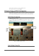
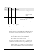
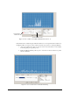
This menu controls the duration of the alarm lights and alarm sounder via the Alarm Light
Duration and Alarm Sounder Duration sliders. The Short, Medium, Long and Steady radio buttons
control the repetition rate of the enunciators. The Alarm Volume slider controls the volume of the
alarm sounder. These parameters may be tested by checking the Lights and/or Sound box and
pressing the Test button. After adjusting the parameters as desired, press the Apply button to have
the new parameters take effect.
All other switches in this tab are not used for the TR4215 board.
After setting the switches as desired, click Apply.
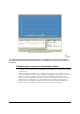
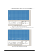
Antenna Settings Submenu
This submenu contains a redundant set the digital potentiometers that control transmitter power,
software receiver gain level and hardware receiver gain level for the PAB and SAB. The same
controls can be found in the Analog View page. There are also new features in this submenu used
by the TR4215 board not found in both TR4200 and TR4215 boards.
TX Maximum Power Switch
Each digital potentiometer controls the output power for a given pedestal with Antenna 1 tab
controlling the PAB and Antenna 2 controlling the SAB. The range is 0-31 and for most cases
each pedestal will be set for full power output (31).
RX Gain
Each digital potentiometer controls the software gain for a given pedestal with Antenna 1 tab
controlling the PAB and Antenna 2 controlling the SAB. This software gain adjusts the gain
within the DSP algorithms after the tag signal is digitized. The range is 0-31 and for most cases
each pedestal will be set for full gain (31).
RX Hardware Gain
Each digital potentiometer controls the hardware gain for a given pedestal with Antenna 1 tab
controlling the PAB and Antenna 2 controlling the SAB. This hardware gain adjusts the gain of
the final amplifier before the tag signal is digitized. The range is 0-31 and for most cases each
pedestal will be set for full gain (31). This setting replaces the gain jumper used to avoid
saturation for the TR4200 and TR4210.
Port Control Switch
This checkbox activates controls used to either enable/disable a port or certain parameters of the
port such as controlling transmitting and/or receiving on a port.
• RX Checkbox – When checked the receiver on this port is enabled and operates as
normal. For cases when a sweeper mode is needed, this checkbox would be unchecked
disabling tag detection for this port. This condition just logically disables the receiver, but
physically still receives the tag signal not using the result as a tag alarm. This is desired
because we still need to detect big tag signals for TX control. More information will be
given later in this document about the different antenna modes (sweeper vs. non-sweeper).
• TX Checkbox – When checked the transmitter for this port is enabled and operates as
normal. Again for cases when a sweeper mode is needed, this checkbox would be
unchecked physically disabling the transmitter for this port. More information will be
given later in this document about the different antenna modes (sweeper vs. non-sweeper).