
Installation Guide Part 3

NGL FX Installation Manual Rev. *
62 of 84
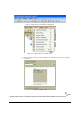
Switch Settings Band Tab
The TR4215 is different from previous pulse-listen transceivers as it does not use jumpers, DIP
switches, or potentiometers to modify its configuration. However, there are jumpers used to set the
basic frequency tuning (8.2 vs. 9.0) for the transmitter output and terminating the RS-485 for the
sync connection. All operating parameters for the TR4215 are controlled by the DMS software
application running on a PC that can only be connected to the Reader via serial Badge port (J48 of
Main). For detailed information, see the Field Service DMS User’s Guide.
The only configuration supported for the TR4215 is the ECO system using only one set of
electronics to drive two pedestals via passive A1096 couplers. This allows a typical aisle width of
up to 1.8m (6 feet).
System Address
Since there is no inter-pedestal communications or Ethernet for the TR4215 there is no needed for
these addresses.
Tag Band
For information about tag bands please refer to The section "Application-Based Detection Modes"
in Chapter 6.
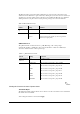
Band Edge
The Phase Array/Reduce Pulse Width mode only transmits four different frequencies four times
consecutively therefore the Band Edge Selection setting 1-14 has no effect.
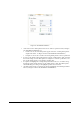
Table 5: Band Edge Selection
Switch Setting Function
Band Edge
Selection
1-14 No effect
0-7 High band bins eliminated
8-15 Low band bins eliminated
0-15 Full band detect
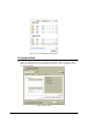
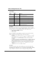
Filter View
The Filter View switch selects different digital signal processing views A, B, C, or D.
• Filter selection A: Raw Data only
• Filter selection B: Data following Peak Removal Filter
• Filter selection C: Data following Moving Average Filter
• Filter selection D: Data following Background Subtraction
As a rule of thumb, as you move progressively from View A through View D, noise is seen to be
suppressed, while resonance is enhanced. Stationary resonance is commonly identified according
to data signature, which is present in View C but absent in View D. Unlike the TR4024, these
views are passive and do not affect tag processing.
Master/Submaster/Repeater
The master/submaster mode is used to allow multiple sets of electronics to operate without
collisions when each set of electronics or pedestals are in close proximally of each other. For this
condition, one set of electronics will be set to master and a sync cable from the master shall be
connected to a second set of electronics which is set to submaster. The sync cable can be extended
by daisy chaining from each additional submaster in the network.