
Installation Guide Part 3

NGL FX Installation Manual Rev. *
61 of 84
low resonance close to the operating frequency range. These problems could be resolved by
increasing the gap (Sampling Holdoff) between transmit and receive cycles.
The TR4215 board does not support inter-pedestal, Ethernet or modem functionality. For this
reason all setting related to these feature will not be include in this document.
The Reader is powered by an external +24Vdc power supply. This power supply can power up to
a maximum of two antennas when these system have a reader driving each antenna.
The maximum power allowed within the systems would be limited by the +24V power supply,
which is 2.1A maximum.
The +24VDC is supplied by an external AC-DC converter listed below:
• Checkpoint Part 7116509 - Globetek 559-ES(R) -2.1A
An alternate can be used in Europe:
• Checkpoint Part 7210084 - EOS/Celetron Part LFZVC65SG24E -2.7A
• Second Source – Friwo Part 1825898 -2.2A
System Description
2 Loop/3 Loop
The TR4215 circuit board (PCB) is a transceiver typically using a pedestal consisting of a 3-loop,
2-loop and a 1-loop antenna. The PCB transmits and receivers on the 2-loop and 3-loop antenna of
the pedestal in which it is installed (primary pedestal) using just TX1/RX1 port. This is done by
splitting and combining this port via the passive A1096 coupler board. The 1-loop antenna of that
pedestal is used as a shield that is tied to ground. This technique provides the system with different
views of the detection field, allowing the system to improve detection by minimizing the holes
typically found at the crossbars of typical swept antennas.
During each frame, the transmitters (TX1 and TX2) emit thirty-two bursts of RF energy, four per
each of four frequency “bins” executed twice. A bin consists of two “receive” cycles and two
“blast” cycles; a “blast” is a transmit cycle followed by a “receive” cycle. The receive cycle
consists of a signal channel and a noise channel in that order. During the signal channel, the
system detects the tag ring down and during the noise channel, the system processes the noise. For
both channels the system does not transmit but only receives tag signal and ambient noise.
Processing the noise channel allows the system to establish the baseline noise level of the
environment for later comparison. The system then transmits or “pulses” the field and then
receives or “listens” for an echo of a tag signal.
A tag response need only be present on one of the antennas to cause an alarm. The switching
between antenna coil sets minimizes the size of detection holes at the null points of the RF field.
Although the TR4215 is considered a replacement for the TR4024 and TR4022 PCB’s, there are
still some compatibility issues between the two boards.
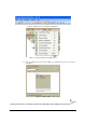
System Configuration
The TR4215 is different from previous pulse-listen transceivers as it does not use jumpers, DIP
switches, or potentiometers to modify its configuration. However, there are jumpers used to set the
basic frequency tuning (8.2 vs. 9.0) for the transmitter output and terminating the RS-485 for the
sync connection. All operating parameters for the TR4215 are controlled by the DMS software
application running on a PC that can only be connected to the Reader via serial Badge port (J48 of
Main). For detailed information, see the Field Service DMS User’s Guide.
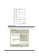
The only configuration supported for the TR4215 is the ECO system using only one set of
electronics to drive two pedestals via passive A1096 couplers. This allows a typical aisle width of
up to 1.8m (6 feet).