
Installation Guide Part 1

NGL FX Installation Manual Rev. *
32 of 84
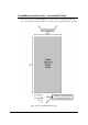
Unshielded FX Antenna
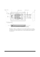
The component list and wiring instructions for connecting the Unshielded FX system antenna loop
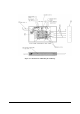
to the potted matching board are below. Figure X***29 details the unshielded potted matching
board’s electrical connections before potting is done.
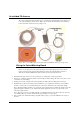
Figure X***: Potted Matching board and Unshielded FX Antenna Loop Components
Wiring the Potted Matching Board
Please note the placement of the potted matching board 15.24cm [6in] in front of the antenna
instead of in between the antenna. The matching board for the Unshielded FX system has a
different part number (CKP P/N 7113880), but has the same physical dimensions.
1. Determine the length of wire to be cut for antenna loop configuration(s). Cut long if unsure.
2. Insert the cross linked polyethylene-jacketed wire through the Teflon tubing. Allow the excess wire to stick
out at either end of the tubing.
3. Starting about 3.8cm [1.5in] from the potted matching assembly, place the tubing in the cut trough.
4. Install the wire in the trench, feeding it around until the loop is complete. The antenna feed point will be
30.5cm +/- 2.5cm [12in +/- 1in] when trimmed. No extra wire is allowed because it may affect tuning.
Note*: The Teflon tubing should be one continuous piece beginning at the assembly, through the cut for the
pigtail, through the antenna loop cut, and back through the pigtail cut. One tube is positioned above the
other at the pigtail location.
Note*: Keep exposed wire (not in Teflon tubing) to a minimum leaving just enough to allow the wire nuts
to be installed. The exposed wire should measure approximately 3.81 cm [1.5in].
5. Next, seal the ends of the Teflon tubing completely with hot glue to prevent the infiltration of concrete or
moisture.