
Installation Guide Part 1

NGL FX Installation Manual Rev. *
30 of 84
Antenna Wiring
Recall the Potted Matching Board installation and wiring differs between Shielded and Unshielded
FX systems. Instead of locating it in a separate cavity, the Shielded FX matching board is placed
in the top center between the assemblies (or directly beside it, for a single loop). After successful
hardware installation, the next step is wiring the antenna(s) to the matching board.
Shielded FX Antenna
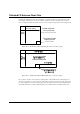
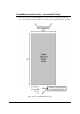
Figure X below shows the proper wiring of the Shielded FX system.
***Graphic of Shielded system wired to PMB.
Figure X***28: Shielded FX system Antenna Panel
Note: If this is a single loop configuration, use the right pair of short and long antenna wires for
the loop (right wires are with potting material facing up and wires exiting the potted matching
assembly towards you). Trim the unused antenna wires at the potted matching board assembly.
Wiring the Potted Matching Board
Perform the following to wire the Potted Matching Board (CKP P/N 7193007) to the Shielded FX
antenna system:
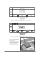
1. Connect the antenna wire to the 0.3m [1ft] wire adjacent to it (wire on the right side of the
potted matching board with the potting side up) in the potted matching assembly using one of
the provided wire nuts.
2. Strip the wire leads about 1.2cm (½”). Next, without pre-twisting the leads, align the wire
conductors and then twist a wire nut onto each connector until hand tight.
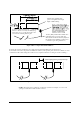
3. Apply excess sealant in and around conductors. This forms a tight connection that will not fail
once buried in the concrete. Refer to the “FX Antenna Floor Cuts” section for details on the
placement of the potted matching board.
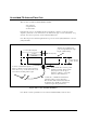
The external and internal wiring before potting of the matching board (P/N 7193007) is displayed
in Figure X***. Item 3 is the 15m [50ft] cable coming from the interface board. Item 4 displays
the connections from J8 and J2 which are connected to the FX antenna. The fly wires from these
ports are 0.3m [1ft] in length.