
Installation Guide Part 1

NGL FX Installation Manual Rev. *
29 of 84
C H A P T E R
4
WIRING
Overview
This chapter instructs on the wiring of the entire floor system, beginning with the FX antenna and
potted matching board* wiring, then moving to the transmission line and its proper connection to
the electronics enclosure. Figures show the proper wiring of the A1111 Interface Board and DC
Power Supply. Lastly, the system-specific (sync, IPC and alarm group) wiring schemes are shown.
W
ARNING
*:
This system uses TR4215
†
electronics with firmware version 4.00 or higher. It is
critical to note that ONLY TR4215 electronics can be used in conjunction with this system.
It is also critical that DMS version 1.8.31 or later be used to configure the system.
The outline below is a sequence of the FX system wiring procedures.
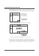
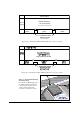
1. Antenna Wiring
a. Wiring the Shielded FX Panel to the Potted Matching Board
b. Wiring the Unshielded FX antenna to the Potted Matching Board
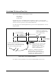
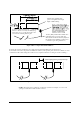
2. Electronics Chassis
a. Transmission Line Wiring to the A1111 board
b. DC Power Supply wiring
c. Sync and Alarm Group ***waiting for info
d. Lights and Sounder
e. Inter-pedestal communication