
Installation Guide Part 1

NGL FX Installation Manual Rev. *
24 of 84
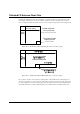
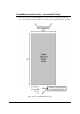
Figure 24X***: Single-Antenna Installation
Note: The floor trench specifications for a single-antenna Unshielded FX system are shown above.
Note: Details on how the components are installed are written (on the specific parts) shown above. Please see notes
on transmission line cable routing and conduit as note (complete instructions on wiring are found in “Wiring”).
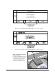
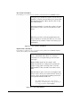
20.3cm [8in] spacing to adjacent loop
Figure 25X***: Four-Antenna Installation
NOTE*: These kits can be combined to create larger systems. For example, to cover a 12 ft
opening, a 4 ft kit and an 8 ft kit would be ordered.
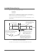
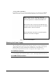
Antenna wire, including feed
point, is encapsulated in a single
length of Teflon tubing
.
15.24m [50ft] of 100 Ω direct burial rated
transmission line to remote electronics.
Wire should remain at least 0.6m [2ft] from
the antenna wires. Install in conduit in new
construction (pass along instructions).
Location of Antenna Feedpoint
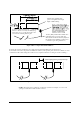
Excess is 30.5cm ± 2.5 cm [12in ± 1in] long.
Dress wires on top of each other in floor cut
and seal ends of tubing with hot glue.