
Installation Guide Part 1

NGL FX Installation Manual Rev. *
23 of 84
Unshielded FX Antenna Floor Cuts
There are three (3) NGL Unshielded FX kits available:
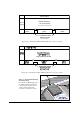
• Two Antenna
• Single Antenna
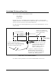
• Four Antenna
Determine the version to be installed and then work with the contractor. Use the appropriate
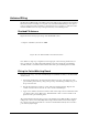
diagram to plan the floor cuts. Antenna floor cuts will measure approx. 5/16” wide and 3/4” deep
(0.79cm and 1.9cm, respectively) for the Unshielded FX system.
Note: The range for the antenna length dimension goes from 91.4cm [36in] minimum to 113.7cm
[44in] maximum.
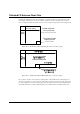
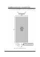
Figure 23X***: Two-Antenna Installation
Note: The floor trench specifications for two-antenna Unshielded FX systems are above.
[
36in]
min
61cm
±
1.9cm
[24in ±0.75in]
113.7cm [44.75in]
max
20.3cm
[8in]
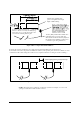
Cavity cut into floor to house potted
matching enclosure. Allow 15.2cm
[6in] of space from cut edge to
antenna loop. Refer to section X*
below for cutout dimensions.
15.24m (50’) of 100 Ω direct burial rated
transmission line to remote electronics.
Wire should remain at least 0.6m [2ft] from
the antenna wires. Install in conduit in new
construction (pass along instructions).
Location of Antenna Feedpoints
Excess is 30.5cm ± 2.5 cm [12in ± 1in] long.
Dress wires on top of each other in floor cut
and seal ends of tubing with hot glue.
Antenna wire, including feed
point, is encapsulated in a single
length of Teflon tubing
.
91.4cm