
Installation Guide Part 1


NGL FX Installation Manual Rev. *
20 of 84
Parts
Quantity will vary according to site.
18 AWG 2-conductor (STP)
CAT5e cable
22 AWG 4-conductor (STP) (5594)
1/2” Anchor Bolts
*DekDuct (wire chase)
*Wiremold (1500 or 2600 series)
*Wiremold anchor bolts Note:
Note***: Wire routing methods will vary by installation.
Note***: Complete parts lists with OEM Part Numbers are included in the Appendix*** section
Part lists.
Installation Outline
Follow this sequence to successfully install the components and validate system operation:
1. Determine optimal antenna placement:
a. Perform a site survey now or
b. Use the results of a previous survey.
2. Determine power supply requirements and the ideal location for system electronics.
3. Physically install the antenna(s).
4. Connect the antenna wiring.
5. Install the peripherals.
6. Configure the system using DMS.
FX Antenna Installation
Antenna installation and tuning is performed by trained Checkpoint personnel. You have already
determined the number and size of the panels or ground loops, or you recently received this key
information from a prior survey. If you are unsure of any specifics, contact Checkpoint Project
Management.
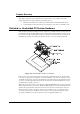
Install the antenna(s) in the proper location(s) discovered during the site survey.
During Construction
In the event of a new construction, please convey the following information to the site contractors
(construction team foreman) or manager responsible for pouring the concrete:
• Location where antenna pan(s) will be placed (define a reference point).
• The exact dimensions of the pan(s); provide them with the “Floor Cut” diagrams below.
• The bury depth and length of the conduit (PVC), installed ahead of time, to route the
transmission cable.
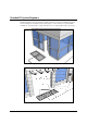
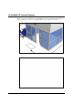
After Construction
Convey the following instructions to the contractor for any existing sites (i.e. where cuts are made).
Refer to the diagrams from the appropriate “Floor Cut” sections corresponding to the required FX
system type and antenna configuration(s).