
Installation Guide Part 1

NGL FX Installation Manual Rev. *
19 of 84
C H A P T E R
3
PHYSICAL INSTALLATION
Chapter Outline
This chapter offers diagrams and lists steps for physical installation of the major system hardware:
1. Requirements: Lists tool and part requirements for a typical installation.
2. Installation Outline: Lists all of the basic installation steps as a sequence.
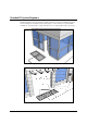
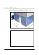
3. Cut Diagrams: How to plan/make cuts for proper installation of the antenna assembly,
potted matching board, and install/route the wiring of the transmission line cable.
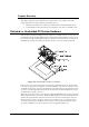
4. Mounting the Electronics Enclosure: Lists the basic steps for installing the enclosure.
Requirements
Tools
The following tools are required for FX system installations:
Arrow T-25 Staple Gun
Diagonal wire cutter
Hammer drill with 3/16” and 1/2” bits
Extension cord
Tape Measure
Hammer
Marker, Black Felt
Ratchet driver with 9/16” socket
Screwdrivers: mini, regular and #2 Phillips
Hacksaw
Utility knife
Wire Snake
Wire Strippers
Wrench, combination end 9/16”
TR4215 FX 2012 Installation Manual (This manual)
TR4215 Tuning Procedure (This manual)
Checkpoint Systems Field Service Diagnostic Management Software (DMS version
1.8.31 or later version) installed on a laptop with the appropriate cables. DMS is an
application developed to install and configure TR4215 boards via serial connections.
DMS provides for firmware updates without replacement of microchips.