
Installation Guide Part 1

NGL FX Installation Manual Rev. *
17 of 84
***FX Performance
Environmental Considerations ***
FX systems are not approved for operation in a wet environment, so this procedure is meant for
dry installations only. The ideal location of the antenna(s) is where the water table does not
interfere (i.e. water drains away from in-floor assembly and does not pool above).
Note***: It is recommended that if the slab is on grade that the concrete be poured above a vapor
barrier to prevent moisture from rising, thus keeping the slab dry.
The store's architect will recommend the maximum permissible loading in the floor area where
FX-Shielded antenna panels are installed. The architect must consider such factors as anticipated
traffic over the floor and the material characteristics of the flooring (if covered above concrete).
The weight of the floor should not rest on the antenna(s).
The guidelines included in this guide assume installation into concrete (typical), but the antennas
may be placed above concrete if finished flooring, such as hardwood, laminate, tile or stone, will
conceal. With all installations, the concrete and other materials above the antenna(s) cannot be
metallic. For example, wire mesh cannot be used for reinforcement above the concrete. Tile grout
and the mortar used to fill the antenna trenches MUST BE non-metallic and non-magnetic grout.
As for the electronics, typical indoor environmental considerations must be met:
Operating temperature is 0°C to +40°C [32° to 104°F]. Permissible humidity range is 10 to 75%.
The UV Exposure requirement is the electronics enclosure must be located where it is not exposed
to direct sunlight. However, locating the enclosure where it will be exposed to sunlight through
glass is acceptable.
Perform a Dry Run
A “dry-run” can determine where potential problems might occur. The following procedure
simulates an FX antenna in place to ensure proper final configuration of the complete system:
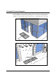
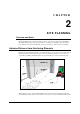
1. Build the Floor Loop Jig. The device consists of a piece of cardboard that is 0.9m x 1.5m
[3ft x 5ft].
a. Cut out a rectangular piece of cardboard measuring 0.9m x 1.5m [3ft x 5ft].
b. Cut at least 14m [13.33ft] of 18 AWG Stranded wire, then form a rectangular loop
that measures 61cm x 112cm (24” x 44”). Approximately 0.3m [1ft] of excess wire
on both sides of the loop remains \.
c. Duct tape the loop to surface of the cardboard, centering it appropriately.
d. Allow extra wire to extend from the jig in the middle of one of the 61cm [24in] ends
of the rectangle or the corner. Twist together the two ends until it forms a braid. Do
not create more than 2 turns per 2.5 cm [2 turns per in].
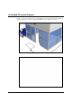
2. Plug the loop terminals into X device. ***specifics to the connection or electronics contol
settings? Then power on the system. Test possible in-floor locations…
Content to work with***
Test by moving the Floor Loop Jig from opening to opening; shift from Side to side while
monitoring noise, see Chapter 6: Tuning*** until a suitable location is found.
Typical performance --- measurements , different detection heights…