
Installation Guide Part 1


NGL FX Installation Manual Rev. *
16 of 84
Common interfering elements and their minimum distances from an FX antenna are listed below:
Expansion Joints: The minimum distance from an expansion joint is 0.6 m [2 ft].
Vertical Cabling: The minimum distance from vertical cabling is 2.4 m [8 ft].
Metal Wall Studs: The minimum distance from a metal wall stud is 0.9 m [3 ft].
Inward and Outward Swinging Doors (Metal): The minimum distance from a manual
swinging metal door is 0.6 m [2 ft].
Note: The antenna must not be located below door when it is fully opened. Locate the FX
system components beyond the door – with a minimum clearance gap of 0.3 m [12 in].
Sliding Doors (Metal): The minimum distance from a metal sliding door is 1.2 m [4 ft]
Tagged Merchandise: The minimum distance from any tagged merchandise is 1.8 m [6 ft]
Note*: For details about location of other systems, such as CP IX/D11 Deactivators, that may
interfere with FX system operation, see appendix section X-Y***.
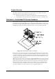
Determining the Electronics Location
FX antennas connect to the electronics enclosure, an integral device responsible for radio signal
control and alarm detection. This enclosure and its power supply are mounted remotely, and
environmental constraints must be taken into account. Determine an approximate location of the
electronics enclosure during the Site Survey.
Note*: The power supply can be mounted adjacent to the electronics enclosure, but this is not a
requirement.
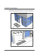
Identify a location that is no further than 12.2m (40 linear-feet) or 15.2m (50 cable-feet) to allow
for bends in the conduit run. The electronics enclosure is usually wall-mounted approximately
1.8m [6ft] above the floor to reduce RF-interaction between the electronics enclosure and any
wiring in the ceiling or floor. Electronics mounted in the ceiling or rafters can potentially have a
high RF-interaction with the surrounding environment, and therefore, may not perform optimally.
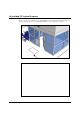
Both the electronics enclosure and power supply are plenum-rated and can be installed above a
drop ceiling or in HVAC areas. Determined whether or not this is necessary during the site survey,
because the hood kit must be ordered separately. If the power supply is going to be located in the
plenum, the Power Supply hood kit must be installed by a licensed electrician (CKP P/N 7367100)
(GS-599MC-KIT(R).
***Note: Another option is to install the electronics enclosure in the plenum and locate the power
supply outside the plenum (below the drop ceiling).
During the following evaluation you can place the electronics enclosure and power supply on the
floor, but strive to locate the electronics near their final locations (to avoid unintended noise later).
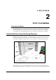
Determining the Appropriate System Type
It is the responsibility of Checkpoint Field Service Personnel (and/or Project Management) to
identify environmental complications that would prevent any EAS system from being installed
and operating properly. After arriving at the site, evaluate the surroundings for possible locations
of in-ground antennas. Look for environmental factors that may affect the system, such as wiring,
lighting, and floor construction. In particular, metal pan flooring (slab on metal deck) will effect
RF detection; buildings with metal flooring are unlikely to be suitable for unshielded installations.
The procedure known as a “dry run” helps you determine if the less-costly Unshielded FX system,
which is more susceptible to noise, is the appropriate FX system type. Unshielded systems are
installed in situations where coupling to metallic objects in the floor is not an issue.