
Installation Guide Part 1


NGL FX Installation Manual Rev. *
11 of 84
Chapter Overview
This chapter explains the system hardware and compares the two types of FX systems. This
general information is useful for planning and training purposes.
1. Hardware: Lists differences in hardware for the Shielded and Unshielded FX systems.
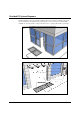
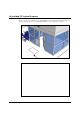
2. System Diagrams: Shows the basic layout of hardware components for each FX system.
Shielded vs. Unshielded FX System Hardware
Both Shielded and Unshielded FX systems are designed to be installed in the floor and provide an
invisible EAS system. The main difference between the shielded and unshielded versions is the in-
floor antenna assembly. Shielded FX system uses a metal floor pan and ferrite tiles, which prevent
the RF detection field from emitting downward into the floor or into the antenna panel itself.
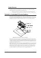
Figure 1-2: Shielded FX Antenna Layer Diagram
Both systems consist of a transceiver-based system using pulse/listen technology, allowing them
to work in a single antenna configuration. Some main hardware components are common to each,
specifically the electronics enclosure and transmission line. The antenna for the unshielded system
is a wire loop ran through Teflon tubing, whereas the antenna for the Shielded FX system is a pre-
assembled unit (see Figure 1-2 above).
With both systems, the antenna is wired directly to the Potted Matching Board, another component
that is installed in the floor (i.e. buried). The Potted Matching Board provides the link between the
antenna wiring and transmission line that connects to the remotely located electronics enclosure.
The electronics enclosure is designed to ensure proper ventilation in a non-condensing 0-40
O
C
environment. The wiring for the FX electronics system is a low-voltage, limited-energy system
(operating at 24VDC or less). All wiring must conform to applicable wiring codes.