NGL FX 2012 Installation Manual Document Version 00 P/N 7360602
NGL FX 2012 Installation Manual Copyright © 2012 by Checkpoint Systems Inc. Released August 31, 2012. Published by: Checkpoint Systems Inc. 101 Wolf Drive Thorofare, NJ 08086 For use with the Checkpoint NGL FX 2012 System both Shielded and Unshielded in-floor models. Trademarks Checkpoint is a registered trademark of Checkpoint Systems, Inc. Checkpoint, Liberty, Evolve, and VisiPlus are registered trademarks of Checkpoint Systems, Inc. All rights reserved.
Statements • • • • • • • • • • • The device(s) may only be used for the intended purpose designed by for the manufacturer. Unauthorized changes and the use of spare parts and additional devices which have not been sold or recommended by the manufacturer may cause fire, electric shocks or injuries. Such unauthorized measures shall exclude any liability by the manufacturer. The liability-prescriptions of the manufacturer in the issue valid at the time of purchase are valid for the device.
Important Information to our Users in North America FCC Regulatory Compliance Statement Checkpoint Systems, Inc., offers Electronic Article Surveillance (EAS) or Radio Frequency Identification Products that have been FCC certified or verified to 47 CFR Part 15 Subparts B/C. Appropriately, one of the following labels will apply to the approval: NOTE: This equipment has been tested and found to comply with the limits for a class A digital device, pursuant to Part 15 of the FCC Rules.
Industrie Canada Conformément à la réglementation d'Industrie Canada, le présent émetteur radio peut fonctionner avec une antenne d'un type et d'un gain maximal (ou inférieur) approuvé pour l'émetteur par Industrie Canada. Dans le but de réduire les risques de brouillage radioélectrique à l'intention des autres utilisateurs, il faut choisir le type d'antenne et son gain de sorte que la puissance isotrope rayonnée équivalente (p.i.r.e.
Important Information to our Users in Europe CE Regulatory Compliance Statement Where applicable, Checkpoint Systems, Inc., offers certain Electronic Article Surveillance (EAS) products that have CE Declarations of Conformity according to R&TTE Directive 99/5/EC, EMC Directive 2004/108/EC, and Low Voltage Directive 2006/95/EC.
Table of Contents STATEMENTS............................................................................................................................................................3 GUIDE CONVENTIONS ...........................................................................................................................................3 TABLE OF CONTENTS ............................................................................................................................................
WIRING 24VDC POWER SUPPLY ..............................................................................................................................41 SYNCHRONIZING, SLAVING AND SYSTEM PROXIMITY ...........................................................................42 WIRING PERIPHERALS ..............................................................................................................................................42 CHAPTER 5NETWORKING AND PERIPHERALS ...................................
NOISE SOURCES .....................................................................................................................................................70 ANALOG VIEW........................................................................................................................................................71 TYPICAL TUNING PROCEDURE .................................................................................................................................
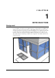
CHAPTER 1 INTRODUCTION Background For years FX Floor Systems have been installed using Gen One Liberty Electronics (TR4024), but with the development of the Next Gen Liberty or NGL (TR4215) Electronics, it has been found using the new generation of electronics provides better immunity to noise.
Chapter Overview This chapter explains the system hardware and compares the two types of FX systems. This general information is useful for planning and training purposes. 1. 2. Hardware: Lists differences in hardware for the Shielded and Unshielded FX systems. System Diagrams: Shows the basic layout of hardware components for each FX system. Shielded vs. Unshielded FX System Hardware Both Shielded and Unshielded FX systems are designed to be installed in the floor and provide an invisible EAS system.
Shielded FX System Diagrams FX 2012 Shielded systems use antenna assemblies which are comprised of a Stainless Steel pan, ferrite shielding tiles, and PVC antenna panels. Figures 1.3 and 1.4 below show Shielded FX installations of varying width covering 1.8m and 2.7m door openings [6ft and 9ft, respectively]: Figure 1.3: Typical Shielded FX 1.8m [6ft] Installation Figure 1.4: Shielded FX 2.7m [9ft] Installation with Component Names NGL FX Installation Manual Rev.
Unshielded FX System Diagrams Figures 1.5, 1.6, and 1.7 display views of an installation for both 1.2m [4ft] and 3.6m [12ft] door opening. Although not shown, a 1.8m [6ft] installation is also possible (see “Layouts”). Figure 1.5: Typical Unshielded FX 1.2m [4ft] Installation Figure 1.6: Typical Unshielded FX 3.6m [12ft] Installation NGL FX Installation Manual Rev.
Coverage width spans from 0.91m [3ft] to 4.88m [16ft] for both Unshielded and Shielded FX systems. The 3.6m [12ft] door opening shown above is created by combining a 1.2m [4ft] and 2.4m [8ft] system together. Grouping multiple installation kits together is possible, but while wider openings can be covered, it requires approval from Checkpoint’s Product Management and confirmation of feasibility during the planning stage (refer to the “Site Survey”*** section below). Figure 1.7: Typical Unshielded FX 3.
CHAPTER 2 S IT E P L A N N I N G Overview and Goals Checkpoint Field Service personnel visit the location to perform a site survey before installation. The initial planning stage is the appropriate time to determine site suitability, where the antenna loops will be located (for maximum EAS protection) and the type of FX system to be installed. Antenna Distance from Interfering Elements Carefully execute antenna placement so environmental factors do not degrade system performance.
Common interfering elements and their minimum distances from an FX antenna are listed below: Expansion Joints: The minimum distance from an expansion joint is 0.6 m [2 ft]. Vertical Cabling: The minimum distance from vertical cabling is 2.4 m [8 ft]. Metal Wall Studs: The minimum distance from a metal wall stud is 0.9 m [3 ft]. Inward and Outward Swinging Doors (Metal): The minimum distance from a manual swinging metal door is 0.6 m [2 ft].
***FX Performance Environmental Considerations *** FX systems are not approved for operation in a wet environment, so this procedure is meant for dry installations only. The ideal location of the antenna(s) is where the water table does not interfere (i.e. water drains away from in-floor assembly and does not pool above). Note***: It is recommended that if the slab is on grade that the concrete be poured above a vapor barrier to prevent moisture from rising, thus keeping the slab dry.
Based on the outcome of the dry run test (i.e. the level of noise when simulating an unshielded system), the decision is made to test with a Shielded FX system or continue with the installation (if results indicate it will perform optimally in the environment). To simulate Shielded FX system operation, the entire antenna assembly (floor panel) is placed on the floor. Testing occurs as before.
CHAPTER 3 P H Y S IC A L I N S T A LL A T I O N Chapter Outline This chapter offers diagrams and lists steps for physical installation of the major system hardware: 1. 2. 3. 4. Requirements: Lists tool and part requirements for a typical installation. Installation Outline: Lists all of the basic installation steps as a sequence. Cut Diagrams: How to plan/make cuts for proper installation of the antenna assembly, potted matching board, and install/route the wiring of the transmission line cable.
Parts Quantity will vary according to site. 18 AWG 2-conductor (STP) CAT5e cable 22 AWG 4-conductor (STP) (5594) 1/2” Anchor Bolts *DekDuct (wire chase) *Wiremold (1500 or 2600 series) *Wiremold anchor bolts Note: Note***: Wire routing methods will vary by installation. Note***: Complete parts lists with OEM Part Numbers are included in the Appendix*** section Part lists. Installation Outline Follow this sequence to successfully install the components and validate system operation: 1.
Shielded FX Antenna Floor Cuts Installing the FX antenna panels in an existing store requires a trough to be cut in the floor. If the site is under construction, it is easier to mold the system into the floor (explained above). These floor cut diagrams include the details on the size of the trough cuts required for each configuration. 101.6cm [40in] 91cm [36in] FLOOR TROUGH – 7.
274cm [108in] FLOOR TROUGH – 7.6 cm [3in] Deep 91cm [36in] Trough must be smooth and level 91cm [36in] 91cm [36in] 91cm [36in] FX Shielded Potted Matching Board (CKP P/N 7193007) Figure 7X***: FX Shielded w/Potted Matching Board for 2.7m [9’] Opening Figure 8X***: FX Shielded w/Potted Matching Board for 3.
Unshielded FX Antenna Floor Cuts There are three (3) NGL Unshielded FX kits available: • Two Antenna • Single Antenna • Four Antenna Determine the version to be installed and then work with the contractor. Use the appropriate diagram to plan the floor cuts. Antenna floor cuts will measure approx. 5/16” wide and 3/4” deep (0.79cm and 1.9cm, respectively) for the Unshielded FX system. Note: The range for the antenna length dimension goes from 91.4cm [36in] minimum to 113.7cm [44in] maximum.
Antenna wire, including feed point, is encapsulated in a single length of Teflon tubing. Location of Antenna Feedpoint Excess is 30.5cm ± 2.5 cm [12in ± 1in] long. Dress wires on top of each other in floor cut and seal ends of tubing with hot glue. 15.24m [50ft] of 100 Ω direct burial rated transmission line to remote electronics. Wire should remain at least 0.6m [2ft] from the antenna wires. Install in conduit in new construction (pass along instructions).
Potted Matching Board Cuts – Unshielded FX Only The cavity for the potted matching PCB is to be placed 15.2cm [6in] from the antenna loops, centered between them. Plan the cuts for this cavity using the specifications below: Figure X***: Potted Matching Board Cavity NGL FX Installation Manual Rev.
Figure X***27: Unshielded Floor Trench Specifications Mounting the Electronics Enclosure Instructions for locating the Electronics Enclosure are included below. It is important that the electronics enclosure be located no further than 12.2 linear-meters [40 linear-feet] from the antenna panels to allow for bends in the 15.2 cable meters [50 cable feet] run. The enclosure, which weighs 5.17kg [11.4lbs], has keyhole slots at its edges to facilitate mounting to the wall surface.
Wood Surface Installation For mounting to wood, use a #7 x ½” (0.38cm x 1.3cm) hex head screw (CKP P/N 7939172). Using the proper diameter bit, drill a hole into the base material to a depth of at least 0.6cm [1/4”] deeper than the embedment required. Blow the hole clean of dust and other material. Select the installation tool and drive socket to be used. Insert the head of the screw into the hex head socket driver.
Concrete Surface Installation For mounting to concrete, use a 5/16” lead anchor and a #12 x 1 ½” panhead screw (CKP P/N 366291). Lead anchor (0.79cm) is a Power Fastener (P/N 09439). Screw is 0.55cm x 3.8cm. Drill a hole into the base material to the depth required. The tolerances of the drill bit used should meet the requirements of ANSI Standard B212.15. Blow the hole clean of dust and other material. Insert the anchor into the hole until the flange is seated flush with the surface of the base material.
CHAPTER 4 W IR I N G Overview This chapter instructs on the wiring of the entire floor system, beginning with the FX antenna and potted matching board* wiring, then moving to the transmission line and its proper connection to the electronics enclosure. Figures show the proper wiring of the A1111 Interface Board and DC Power Supply. Lastly, the system-specific (sync, IPC and alarm group) wiring schemes are shown. WARNING*: This system uses TR4215† electronics with firmware version 4.00 or higher.
Antenna Wiring Recall the Potted Matching Board installation and wiring differs between Shielded and Unshielded FX systems. Instead of locating it in a separate cavity, the Shielded FX matching board is placed in the top center between the assemblies (or directly beside it, for a single loop). After successful hardware installation, the next step is wiring the antenna(s) to the matching board. Shielded FX Antenna Figure X below shows the proper wiring of the Shielded FX system.
Figure 18: Shielded Potted Matching Board Wiring NGL FX Installation Manual Rev.
Unshielded FX Antenna The component list and wiring instructions for connecting the Unshielded FX system antenna loop to the potted matching board are below. Figure X***29 details the unshielded potted matching board’s electrical connections before potting is done. Figure X***: Potted Matching board and Unshielded FX Antenna Loop Components Wiring the Potted Matching Board Please note the placement of the potted matching board 15.24cm [6in] in front of the antenna instead of in between the antenna.
Figure X***29: Unshielded Potted Matching Board Wiring Note: If this is a single loop configuration, the pair of short and long antenna wires on the right (see FigureX***) are wired to the antenna loop. As shown in the graphic, the potting material side faces up and the wires exit the assembly (towards you). The unused antenna wires are trimmed (see step 4 below). NGL FX Installation Manual Rev.
TR4215 Components and Enclosure Overview Connections to the Electronics Enclosure / reader assembly are listed below. This section describes how to prepare and wire all cables and wires involved in the antenna installation. TR4215 board with all interfaces labeled. A ferrite clip (CKP P/N 7284760) (Fair Rite P/N 044380640) is installed on all TR4024 I/O cables shown below.