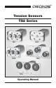
CHECK•LINE BY ELECTROMATIC Tension Sensors TS2 Series TS2 TS2P TS2B TS2H TS2L Operating Manual ®
TABLE OF CONTENTS 1.0 Introduction.................................................................................................. 1.1 Delivery 1.2 Unpacking 02 2.0 Available Models.......................................................................................... 2.1 TS2 Models 2.2 TS2P Models 2.3 TS2H Models 2.4 TS2L Models 2.5 TS2B Models 03 3.0 Operating Procedures.................................................................................. 3.1 Mounting Arrangements 3.
1.0 INTRODUCTION The TS2 Series of universal tension sensor accurately measure the running tension of wires, cables, yarns, fibers and similar process material. 2.1 Delivery • Sensor (1) • Operating Instructions (1) 2.2 Unpacking Unpack the instrument and inspect it for any shipping damage. Notices of defect must be filed immediately, in writing, at the latest within 10 days on receipt of the goods. 2.
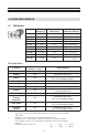
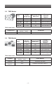
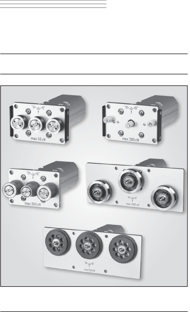
2.0 AVAILABLE MODELS 2.1 TS2 Models Model TS2-50 TS2-100 TS2-200 TS2-500 TS2-1K TS2-2K TS2-5K TS2-10K TS2-20K Tension Ranges [g] 0 - 50 0 - 100 0 - 200 0 - 500 0 - 1000 0 - 2000 0 - 5000 0 - 10 Kg 0 - 20 Kg TS2-50K 0 - 50 Kg *Measuring Head **Factory Width [mm] Calibration Material 64 PA: 0.12 mm Ø 64 PA: 0.12 mm Ø 64 PA: 0.12 mm Ø 64 PA: 0.20 mm Ø 64 PA: 0.30 mm Ø 124 PA: 0.50 mm Ø 124 PA: 0.80 mm Ø 124 PA: 1.00 mm Ø 224 PA: 1.50 mm Ø Steel rope: 1.5mm Ø 224 (7 x 7 x 0.
2.2 TS2P Models TS2P-50 TS2P-100 0 - 50 0 - 100 64 64 **Factory Calibration Material PA: 0.12 mm Ø PA: 0.12 mm Ø TS2P-200 0 - 200 64 PA: 0.12 mm Ø TS2P-500 TS2P-1K 0 - 500 0 - 1000 64 64 PA: 0.20 mm Ø PA: 0.30 mm Ø Tension Ranges [g] Model *Measuring Head Width [mm] TS2P Guide Rollers Line Speed [m/min ... max.] 2000 Ceramic Pins Standard 2.3 Pin Material Oxid ceramic 5.
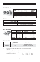
2.4 TS2L Models Tension *Measuring Head Ranges [g] Width [mm] Model TS2L-50 TS2L-100 TS2L-200 TS2L-500 TS2L-1K 0 - 50 0 - 100 0 - 200 0 - 500 0 - 1000 150 150 150 150 150 **Factory Calibration Material PA: 0.12 mm Ø PA: 0.12 mm Ø PA: 0.12 mm Ø PA: 0.20 mm Ø PA: 0.30 mm Ø TS2L Guide Rollers Standard Line Speed [m/min ... max.] 4000 Code T 4000 V-Groove 2.
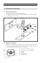
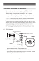
3.0 OPERATING PROCEDURES 3.1 Mounting Arrangements TS2 Series sensors can be mounted in different ways: • Mounting by using the frontplate on a cylindrical hole (cut out 38.5 - 40 mm Ø) • Mounting on a flat platform M4 Screws M3 Screws 3.2 Connector Assignment NOTE: To assure immunity to random noise, the measuring head must be installed so that it is insulated from ground (GND). The shield of the connecting cable must be connected to the metal housing of the connecting plug.
1 2 3 4 5 6 3.3 } Wire assignment of cable TS2-CABLE: 1 (white) Vcc + 15 to 24 V DC regulated 2 (black) Ground Joined 3 (brown) Ground 4 (blue) Signal output – 5 (grey) Signal output + 6 (black) Shield (thick black wire) } Options Code DC Analog output 0 - 10 V DC Code MA Analog output 4 - 20 mA 3.4 Initial Setup • Install the sensor at the desired measuring location. • Connect the sensor to the supplied or existing display unit.
4.0 INTERNAL ADJUSTMENT OF THE SENSORS If the sensor has been delivered with a display unit, the ZERO and GAIN adjustments should only be carried out with the supplied display unit. All tension meters are calibrated with standard material, such as polyamide monofilament (PA), according to the factory procedure; the material path is vertical. Any difference in process material size and rigidity from the standard material may cause a deviation of the accuracy.
! WARNING: When threading the process material through the rollers, follow the material path symbol on the front of the sensor. If a force is applied to the middle sensor roller in the incorrect direction, damage could result. 4. Install the sensor in the desired position at the measuring location using the provided mounting holes. 5. Allow approximately ten minutes for thermal stabilization of the sensor. 6.
4.2 GAIN Adjustment Requirement: ZERO adjustment carried out. 1. Thread the process material through the measuring and guide rollers, following the material path symbol on the front of the sensor. 2. Hang a weight that corresponds to e.g. 95% of the tension range from the process material. 3. Adjust the potentiometer, which you can reach through the GAIN hole in the housing, with a screwdriver (with a point width of max. 1.
5.0 SPECIFICATIONS 5.1 General Specifications Calibration Accuracy Overload Protection Measuring Principle Meas. Roller Deflection Natural Frequency of Measuring Spring Signal Processing Output Signal Option Code DC Damping (fg) Temperature Coefficient Temperature Range Air Humidity Power Supply Housing According to factory procedure For 10% to 100% of range: ± 1% Full Scale Other calibration material: ± 3% Full Scale or better 100% of range Strain gauge bridge 0.5 mm, max. Approx.
6.0 MAINTENANCE AND SERVICE The tension meter is easy to maintain. Depending on operating time and load, the instrument should be checked according to the locally valid regulations and conditions. The use of other test methods than the procedure described in section 4.0 may cause deviating measuring results. 6.1 Cleaning When cleaning the unit, do not use an aggressive solvents, such as trichloroethylene or similar chemicals.
7.0 WARRANTY ELECTROMATIC Equipment Co., Inc. (ELECTROMATIC) warrants to the original purchaser that this product is of merchantable quality and confirms in kind and quality with the descriptions and specifications thereof.
CHECK•LINE ® INSTRUMENTS ELECTROMATIC E Q U I P M E N T C O . , I N C . 600 Oakland Ave.