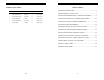
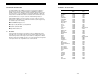
APPENDIX B: SETUP LIBRARY TABLE OF CONTENTS CHAPTER ONE: INTRODUCTION ..............................................................................2 Num Name Comment 1 Gn/AGC Velocity 1 STEEL BASIC 45 0.2330 in/µSec 2 STEEL THRU PNT STD _ 5MHZ HD 15 0.2330 in/µSec 3 STEEL THRU PNT EXT _ 3MHZ HD 14 0.2330 in/µSec 4 ALUMINUM W/GATE _7.5MHZ 45 0.2510 in/µSec 5 PLASTIC W/GATE THK _ 1MHZ CPZT 45 0.0940 in/uSec 6 PLASTIC BASIC _ 2.25MHZ 45 0.
CHAPTER ONE: INTRODUCTION APPENDIX A -VELOCITY TABLE The CHECK-LINE model TI-MVX is a visual A / B scan ultrasonic thickness gauge. Based on the same operating principles as SONAR, the TI-MVX is capable of measuring the thickness of various materials with accuracy as high as ± 0.001 inches, or ± 0.01 millimeters. The principle advantage of ultrasonic measurement over traditional methods is that ultrasonic measurements can be performed with access to only one side of the material being measured.
CHAPTER TWELVE: USING THE UTILITY SOFTWARE 12.1 Turn the TI-MVX on and off using the switch located on the bottom right corner of the keypad. When TI-MVX is initially turned on, a flash logo and blinking lights will be displayed prior to entering into the main measurement screen. Note: This section is primarily written as a basic startup guide only. Computer System Requirements MVXcomm will run on many different operating systems: Windows 95, Windows 98 (1st or 2nd edition), Windows NT 4.
2.2 Probe Zero & Calibration 13) Press the OK key to save the Setup, or ESC to cancel saving the Setup. The next step is to calibrate the TI-MVX to the material and transducer being used. If a sound velocity is not known, the TI-MVX can be calibrated to a known thickness sample. This demo will briefly explain both of these techniques. 14) Finally, press the MEAS key to return to the measurement screen.
1) Press the MENU key once to activate the menu items tab. Press the MENU key multiple times to tab right and the ESC key multiple times to tab left until the SETUP menu is highlighted and displaying the submenu items. 4) Press the OK key to complete the probe zero function, or ESC key to cancel the probe zero function. 2) Use the UP and DOWN arrow keys to scroll through the sub menu items until SAVE is highlighted.
Known Thickness 1) Press the MENU key once to activate the menu items tab. Press the MENU key multiple times to tab right and the ESC key multiple times to tab left until the SETUP menu is highlighted and displaying the submenu items. Sometimes the sound velocity of a material is not known. In this case a sample with a known thickness can be used to determine the sound velocity.
CHAPTER ELEVEN: SETUPS – CREATE, STORE, EDIT, & RECALL 11.1 Introduction to Setups Often times, users are faced with a variety of tasks and applications that are sometimes similar, but often times very different. With a standard thickness gauge, the user would have to recalibrate for each individual application respectively. With all the features of the TI-MVX, the number of potential applications also increases based on ability alone.
2.3 Measure The TI-MVX is now ready to measure. There are four different measurement view options, each with a specific purpose. The steps below outline how to toggle between the different view mode options: Selecting the Measurement View Option 1) Press the MENU key once to activate the menu items tab. Press the MENU key multiple times to tab right and the ESC key multiple times to tab left until the DISP menu is highlighted and displaying the submenu items.
8) Use the CLR key to backspace if necessary. 9) Repeat steps 6 -8 until the Comments are completed. DIGITS: Displays the digital thickness value using a larger font size. This view is useful when the TI-MVX is being used as a basic thickness gauge. Once the view has been selected according to the application requirements, the delay and width of the screen will potentially need to be adjusted, if the view has been set to RF, RECT, or BSCAN.
2) Press the ENTER key to display the digits edit box. 3) Press the UP and DOWN arrow keys to scroll the highlighted value. 4) Press the LEFT and RIGHT arrow keys to scroll the digit locations. 10.6 Editing a grid Once a grid has been created and saved to memory, the user can edit the Comments or Increment Direction at a later time. The following procedures outline this process: 5) Repeat steps 3 & 4 until the DELAY or WIDTH value is correctly displayed.
10.5 Deleting a grid Deleting one grid 1) Press the MENU key once to activate the menu items tab. Press the MENU key multiple times to tab right and the ESC key multiple times to tab left until the DATA menu is highlighted and displaying the submenu items. 2) Use the UP and DOWN arrow keys to scroll through the sub menu items until DELETE ONE GRID is highlighted. 3) Press the ENTER key to display the Grid List Box.
CHAPTER THREE: KEYBOARD, MENU, & CONNECTOR REFERENCE 2) Press the ENTER key to display the Grid View Box. 3.1 3) Press the UP, DOWN, LEFT, and RIGHT arrow keys to scroll the target cell cursor to the desired storage location. Menu Key (Operation & Sub Menus ) 5) Press the ENTER key to save the current reading in the highlighted cell location. 6) Abort the Grid View Box by pressing the MEAS key at any time.
Saving the Grid 3.2 Probe – Menu Zero: The TI-MVX is zeroed in much the same way that a mechanical micrometer is zeroed. If the TI-MVX is not zeroed correctly, all of the measurements made using the TI-MVX may be in error by some fixed value. Refer to the section on page 32, for an explanation of this important procedure. Once all the parameters are set, the user has the option of saving or canceling the new grid.
Two Point: Performs a two-point calibration. This option allows the user to automatically calculate the velocity by entering a second known sample thickness. Refer to page34 for further info. Material: Select the material velocity from a chart of basic material types, when a known sample thickness, or material velocity cannot be obtained. Refer to page 36 for further info. 3.4 DISP (display) – Menu View: Selectable RF wave, RECT (rectified) wave, BSCAN (cross section), and DIGITS (large digits) views.
Setting the Coordinates of the Grid 3.5 TUNE – Menu Gain: Increases or decreases the overall amplitude of the signal. Much like turning the volume up or down on a stereo receiver. Refer to page 47 for further info. Note: A grid is defined by using coordinates to define the Top Left and the Bottom Right corners of the grid. Alpha coordinates are horizontal across the top, and numeric coordinates are vertical down the side.
3.7 SETUP – Menu Open: Displays a list of factory and user defined setups currently stored in memory. These setups can be recalled and used at any time. Refer to page 74 for further info. Save: Provides the user with the ability to save a custom setup that has been modified or created by the user. Refer to page 100 for further info. 5) Press the ENTER key to activate the Alpha Edit Box. 6) Use the UP, DOWN, LEFT, & RIGHT arrow keys to highlight the appropriate alpha characters.
CHAPTER TEN: DATA STORAGE – SETUP, EDIT, & VIEW GRIDS Alarm Status: Toggles alarm mode on or off. Refer to page 75 for further info. 10.1 Introduction to Grid (spreadsheet) format Alarm LO Limit: Gives the user the ability to set the LO limit parameter. If the measurement falls below this value, a red light will illuminate and sound the internal beeper. Refer to page 61 for further info. Data is stored in the TI-MVX in a spreadsheet like format called a GRID. A GRID is simply a table of readings.
3.12 MEAS (measurement mode) Key The MEAS key puts the TI-MVX into it’s primary mode of operation. In this mode, the user has a complete view of the LCD, as well as control of the Hot Menu Functions. These hot functions provide the user with the ability to make crucial adjustments to the display, waveform settings, and grid storage locations without having to search through the menu and sub menu items.
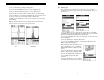
cycle altogether. This peak jump represents a shift of the detection further out in time, resulting incorrect measurements. The material being measured will appear thicker than it actually is. Refer to the diagram: Notice the +/-positions in the diagram. The positive phase is everything above the horizontal center line, and the negative everything below the center line. The TI-MVX uses a zero crossing (flank) method for detection.
3.19 Top & Bottom End Caps Setting the Alarm LO Limit 1) Assuming the ALARM STATUS is ON, use the UP and DOWN arrow keys to scroll through the sub menu items until ALARM LO LIMIT is highlighted. 2) Press the LEFT and RIGHT arrow keys to scroll the value. When the correct alarm value is being displayed, proceed to step 7. 3) Alternatively, press the ENTER key to display the Digits Edit Box. 4) Press the UP and DOWN arrow keys to scroll the highlighted value.
9.4 Alarm Mode CHAPTER FOUR: PRINCIPALS OF ULTRASONIC MEASUREMENT The Alarm Mode feature of the TI-MVX provides the user with a method of setting tolerances, or limits, for a particular application requirement. This feature may be used for incoming material inspections to verify the material received is within the manufacturer specifications. There are two limits, or alarm values, that can be setup in the TI-MVX – ALARM LO LIMIT and ALARM HI LIMIT.
0.010 inch to 9.999” in steel. However, the maximum attainable thickness is much less for more attenuative materials (materials that absorb sound). Using Auto Find 1) Press the MENU key once to activate the menu items tab. Press the MENU key multiple times to tab right, and the ESC key multiple times to tab left, until the UTIL menu is highlighted and displaying the submenu items.
CHAPTER NINE: ADDITIONAL FEATURES OF THE TI-MVX 9.1 Pulse Width The TI-MVX has an adjustable pulse width option, located as a submenu item in the PROBE tab group. Pulse width, refers to the duration of time the pulser is left on. This time results in increased energy sent into the test material. There are three width options (SPIKE, THIN, and WIDE). The SPIKE setting may be desirable for high resolution and general applications to decrease the overall noise.
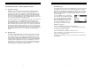
Echo-Echo Mode: The echo-echo mode measures between two reflections. This technique is commonly used to eliminate errors from surface coatings and also to make measurements in multiple layered materials. The disadvantage is that two echoes are needed which requires a much stronger echo Dual Element Transducer (reflection). in Echo-Echo mode Searching for small defects Dual element delay line transducers are especially useful in searching for small defects.
8.2 Setting Up Thru Paint Mode 4.7 Glossary of terms The first thing to note in this section, is that by selecting the transducer type from the list of probes stored in the TI-MVX, a basic echo-echo thru paint configuration is recalled from memory. Each of the transducers in the list contain preconfigured echo-echo settings. However, fine adjustments may be necessary in order to be suitable for your specific applications. These configurations are general setups only.
CHAPTER FIVE: SELECTING THE MEASUREMENT MODE CHAPTER EIGHT: THRU PAINT MEASUREMENT TECHNIQUE 5.1 8.1 I The setup library The TI-MVX contains 64 user configurable preset locations to store custom setups for easy recall. These setups can be optimized for the user’s specific application needs and can also be stored on a PC and transferred bi-directionally using Dakota’s PC interface software included with the instrument.
Alternatively, Gate 2 can be selected from the menus and adjusted as follows: 1) Press the MENU key once to activate the menu items tab. Press the MENU key multiple times to tab right and the ESC key multiple times to tab left until the GATE menu is highlighted and displaying the submenu items. 2) Use the UP and DOWN arrow keys to scroll through the sub menu items until GATE 2 is highlighted. 3) Press the LEFT and RIGHT arrow keys to scroll the value.
5.3 Factory Setup Chart Num 1 2 3 4 5 6 Name STEEL BASIC STEEL THRU PNT STD STEEL THRU PNT EXT ALUMINUM W/GATE PLASTIC W/GATE THK PLASTIC BASIC 5) Press the UP and DOWN arrow keys to scroll the highlighted value. Comment 1 _ 5MHZ HD _ 3MHZ HD _” 7.5MHZ _ 1MHZ CPZT _ 2.25MHZ Gn/AGC 45 15 14 45 45 45 Velocity 0.2330 in/uSec 0.2330 in/uSec 0.2330 in/uSec 0.2510 in/uSec 0.0940 in/uSec 0.0940 in/uSec 6) Press the LEFT and RIGHT arrow keys to scroll the digit locations.
brings all the fine adjustments into consideration, and demonstrates the versatility of having fully functional scope rather than a basic digital thickness gauge. CHAPTER SIX: MAKING MEASUREMENTS The steps involved in making measurements are detailed in this section. The following sections outline how to setup and prepare your TI-MVX for field use. Adjusting Gate1 using the Hot Menus 1) Press the MEAS key once to activate measure menu items.
Selecting the Transducer Type SURFACE NOISE PROBLEM 1) Press the MENU key once to activate the menu items tab. Press the MENU key multiple times to tab right and the ESC key multiple times to tab left until the PROBE menu is highlighted and displaying the submenu items. 2) Use the UP and DOWN arrow keys to scroll through the sub menu items until TYPE is highlighted. 3) Press the ENTER key to display the list of transducer types.
7.6 7) Repeat steps 5 & 6 until the Threshold number is correctly displayed. 3) Press the ENTER key to display the list of stored setups. 8) Press the OK key to set the Threshold and return to the menu screen, or ESC to cancel entering the Threshold. 4) Press the UP and DOWN arrow keys to scroll through the list of setups until the appropriate setup is highlighted. 9) Finally, press the MEAS key to return to the measurement screen and begin taking readings.
6.2 Probe Zero Adjusting the Threshold using the Hot Menus As noted in chapter 3, the probe zero function is a very important and necessary function that must done prior to calibration. It should also be done on a regular basis. If the TI-MVX is not zeroed correctly, all of the measurements taken, may be in error by some fixed value. In order to perform a probe zero, the TI-MVX must be in pulse-echo mode.
Adjusting the Gain using the Tabbed Menus 1) Press the MENU key once to activate the menu items tab. Press the MENU key multiple times to tab right, and the ESC key multiple times to tab left, until the TUNE menu is highlighted and displaying the submenu items. 2) Use the UP and DOWN arrow keys to scroll through the sub menu items until GAIN is highlighted. 3) Press the LEFT and RIGHT arrow keys to scroll the value. When the correct Gain is being displayed, proceed to step 8.
2) Apply a drop of couplant on the transducer. Place the transducer in steady contact on the known thickness location. Be sure that the reading is stable and the repeatability indicator, located in the top left corner of the display, is fully lit and stable. Press the MENU key once to activate the menu items tab. Press the MENU key multiple times to tab right and the ESC key multiple times to tab left until the CAL menu is highlighted and displaying the submenu items.
Adjusting the Delay using the Hot Menus 1) Press the MEAS key once to activate measure menu items. Press the MEAS key multiple times to move right and the ESC key multiple times to move left, until the DELAY cell is highlighted. 2) Press the UP, DOWN, LEFT, and RIGHT arrow keys to scroll the highlighted value. 3) Alternatively, press the ENTER key to display the Digits Edit Box. 4) Press the UP and DOWN arrow keys to scroll the highlighted value.
Note: CHECK YOUR CALIBRATION! Place the transducer back on both calibration points. The thickness readings should now match the known thickness locations. If they are not correct, repeat the steps above. Built in Material Selection 1) Press the MENU key once to activate the menu items tab. Press the MENU key multiple times to tab right, and the ESC key multiple times to tab left, until the CAL menu is highlighted and displaying the submenu items.
H) Hot Menus -Each of the fields located under the display are called the Hot Menu Fields. These fields allow quick control of some of the fine adjustments needed to control the display settings, measurement modes, and grid memory control. All of these fields can be adjusted without having to activate the tabbed menu items and searching through a variety of menus to make adjustments. 7.3 CHAPTER SEVEN: USING THE A-SCAN & B-SCAN DISPLAYS A key feature of the TI-MVX is the waveform display.
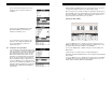
DIGITS VIEW 3) Use the LEFT and RIGHT arrow keys to scroll the view options. Once the appropriate view is displayed, press the MEAS key to return to the measurement screen. 7.2 Display Views RF The RF mode shows the waveform in a similar fashion to an oscilloscope. It shows both the positive and the negative peaks. The peak (either positive or negative) selected for measurement is shown in upper portion of the display.
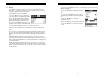
C) Thickness reading – Digital readout of thickness (inches or millimeters). D) B-Scan Display Area – This is the area representing where the B-Scan will be drawn. Notice the range of the area in the diagram at 0.00” – 1.0” respectively. E) Echo Signal – Graphical full waveform representation of the echo signal displayed as an amplitude (vertical or “Y” axis) plotted against time (horizontal or “X” axis), this time is then converted to a physical measurement and displayed according.
Rectified View The rectified A-Scan mode shows half of the waveform. Either the positive or negative peaks are displayed, depending on the polarity selected. This is the preferred display view for flaw and pit detection applications. It’s important to note that a measurement must fall inside the viewable display range in order to see the waveform. However, even if the waveform is outside of the viewable area, a measurement can be taken and viewed on the digital readout.
WARRANTY ELECTROMATIC Equipment Co., Inc. (ELECTROMATIC) warrants to the original purchaser that this product is of merchantable quality and confirms in kind and quality with the descriptions and specifications thereof.
Model TI-MVX VISUAL A/B SCAN THICKNESS GAUGE CHECK•LINE ® ELECTROMATIC E INSTRUMENTS Q U I P M E N T C O ., I N C . 600 Oakland Ave., Cedarhurst, NY 11516–U.S.A.