CHECK•LINE BY ELECTROMATIC OPERATION MANUAL ELECTROMATIC Equip't MINI- MA X BOLT TENSION MONITOR P/N P-156-0002 Rev1.1, September 2005 Visit us on the World Wide Web at www.checkline.com ELECTROMATIC Equipment Co., Inc., 600 Oakland Ave.
CHAPTER 1 WARRANTY AND SAFETY................................................................... 1 1.1 1.2 WARRANTY .......................................................................................................... 1 SAFETY ................................................................................................................ 1 CHAPTER 2 ABOUT THIS MANUAL .......................................................................... 2 2.1 2.2 IF YOU’RE NEW TO ULTRASONICS ....................
6.2 6.3 TRANSDUCER CONTACT REQUIREMENTS ..........................................................35 BOLT END REFLECTORS .....................................................................................36 CHAPTER 7 TRANSDUCER SELECTION ..............................................................38 7.1 SELECTING THE TRANSDUCER ..........................................................................38 CHAPTER 8 MEASURING SYSTEM ZERO (CALIBRATION) .............................39 8.1 8.2 8.3 8.
14.1 14.2 14.3 14.4 14.5 14.6 14.7 INTRODUCTION TO GROUP (SPREADSHEET) FORMAT.....................................150 CREATING A NEW GROUP ................................................................................150 STORING A READING ........................................................................................157 VIEWING STORED MEASUREMENTS AND WAVEFORMS ....................................158 DELETING A GROUP ...............................................................................
MINI-MAX Ultrasonic Bolt Tension Monitor Chapter 1 Warranty and Safety 1.1 Warranty The Dakota Ultrasonics MINI-MAX carries a two year limited warranty. The warranty only applies to MINI-MAX units being operated as described in this manual. Software and hardware failures of the unit will be repaired or replaced at Dakota Ultrasonics discretion. Dakota Ultrasonics will not be held liable for any damage caused, interruption of business, loss of profits, etc., resulting from such failures.
Dakota Ultrasonics Chapter 2 About this manual This chapter is intended to help you make the best use of this manual. Readers may have different knowledge of ultrasonic bolt measurement and may find parts of this manual repetitive or unnecessary. 2.1 If you’re new to Ultrasonics There are a variety of ultrasonic applications currently being utilized in today’s industry. For example weld inspection, thickness measuring, immersion testing of flaws, etc.
MINI-MAX Ultrasonic Bolt Tension Monitor Chapter 3 Quick Start Guide 3.1 Overview This section demonstrates the basic procedures for setting up and measuring bolts using the MINI-MAX. More in depth explanations pertaining to the individual functions and features can be found in the chapters that follow. Here we go! 3.
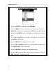
Dakota Ultrasonics Selecting the Quick Start Setup 1) Press the ON/OFF key to power up the MINI-MAX. 2) Press the MENU key once to activate the menu items tab. Press the MENU key multiple times to tab right and the ESC key multiple times to tab left until the SETUP menu is highlighted and displaying the submenu items. 3) Use the UP and DOWN arrow keys to scroll through the sub menu items until OPEN is highlighted. 4) Press the ENTER key to display the list of setups.
MINI-MAX Ultrasonic Bolt Tension Monitor Selecting the Units Note: The Quick Start setup, selected in the previous section, automatically defaults to english units – inches. Follow the procedure below to change the units to metric, if needed. 1) Press the MENU key multiple times to tab right and the ESC key multiple times to tab left until the MATL menu is highlighted and displaying the submenu items. 2) Use the UP and DOWN arrow keys to scroll through the sub menu items until UNITS is highlighted.
Dakota Ultrasonics This section allows the user the ability to select a material from a list of preset material types. Keep in mind that we are measuring elongation only. If your material is not in the list, select a similar material type. When measuring in elongation mode, the measurement consists of a difference equation only (Loaded Length – Unloaded Length = ∆ Length).
MINI-MAX Ultrasonic Bolt Tension Monitor Creating a Group Name 1) Press the MENU key once to activate the menu items tab. Press the MENU key multiple times to tab right, and the ESC key multiple times to tab left, until the DATA menu is highlighted and displaying the submenu items. 2) Use the UP and DOWN arrow keys to scroll through the sub menu items until NEW is highlighted. 3) Press the ENTER key to display the New Group Edit Box.
Dakota Ultrasonics 8) Use the CLR key to backspace if necessary. 9) Repeat steps 6 - 8 until the Group Name is completed. 10) Press the OK key to save the Group Name and return to the Group List Items menu, or ESC to cancel entering the Group Name. Creating a Group Note 1) Use the UP and DOWN arrow keys to scroll through the new Group List Items until NOTE is highlighted. 2) Press the ENTER key to activate the Alpha Edit Box.
MINI-MAX Ultrasonic Bolt Tension Monitor 4) Press the ENTER key to select a character and advance to the next field of the Group Note. 5) Use the CLR key to backspace if necessary. 6) Repeat steps 3 - 5 until the Group Note is completed. 7) Press the OK key to save the Group Note and return to the Group List Items menu, or ESC to cancel entering the Group Note. Selecting the Number of Bolts in the Group Note: A group can contain up to 250 bolts. There must be at least 1 bolt in a group.
Dakota Ultrasonics 6) Press the OK key to save the NUM BOLTS and return to the Group List Items menu, or ESC to cancel entering the NUM BOLTS. Note: If a number greater than 250 is entered, an error message box “VALUE IS OUT OF RANGE” will be displayed. 7) Press the OK key to display the Digits Edit Box and re-enter the NUM BOLTS. 8) Press the OK key to save the NUM BOLTS and return to the Group List Items menu, or ESC to cancel entering the NUM BOLTS.
MINI-MAX Ultrasonic Bolt Tension Monitor 5) Repeat steps 3 & 4 until the NUM READS value is correctly displayed. 6) Press the OK key to save the NUM READS and return to the Group List Items menu, or ESC to cancel entering the NUM READS. Note: If a number less than 1 or greater than 51 is entered, an error message box “VALUE IS OUT OF RANGE” will be displayed. 7) Press the OK key to display the Digits Edit Box and re-enter the NUM READS.
Dakota Ultrasonics 1) Use the UP and DOWN arrow keys to scroll through the new Group List Items until INCR. DIR is highlighted. 2) Use the LEFT & RIGHT arrow keys to toggle the Increment direction NONE, NORTH, EAST, SOUTH, or WEST. 3) When the correct Increment direction is displayed, continue on to the next section “Saving the Group”.
MINI-MAX Ultrasonic Bolt Tension Monitor Saving the Group Once all the parameters are set, the user has the option of saving or canceling the new group. 1) Use the UP and DOWN arrow keys to scroll through the new Group List Items until CREATE NEW GROUP? is highlighted. 2) Press the ENTER key to accept the group parameters, and activate the confirmation screen. 3) Press the OK key to save the New Group, or the ESC key to cancel the New Group setup and return to the DATA menu.
Dakota Ultrasonics in both directions of the approximate length for the detection signal. The approximate length is a very valuable feature that can be used to pin point a specific detection area. This feature will be further discussed later in the manual. Setting the Approximate Length using the Hot Menus 1) Press the MEAS key once to activate measure menu items. Press the MEAS key multiple times to move right and the ESC key multiple times to move left, until the ALEN cell is highlighted.
MINI-MAX Ultrasonic Bolt Tension Monitor 1) Press the MENU key once to activate the menu items tab. Press the MENU key multiple times to tab right, and the ESC key multiple times to tab left, until the AUTO menu is highlighted and displaying the submenu items. 2) Use the UP and DOWN arrow keys to scroll through the sub menu items until APPROX. LEN. is highlighted. 3) Press the ENTER key to display the Digits Edit Box. 4) Press the UP and DOWN arrow keys to scroll the highlighted value.
Dakota Ultrasonics 3.6 Measuring Reference Lengths At this point, the MINI-MAX is setup and ready to start measuring reference lengths. We’ve already setup a bolt group to store the reference length data, and now need to display the group storage locations prior to making measurements. Storing a Reading 1) Press the MEAS key once to activate measure menu items. Press the MEAS key multiple times to move right and the ESC key multiple times to move left until the LOC cell is highlighted.
MINI-MAX Ultrasonic Bolt Tension Monitor Important Note: Always be sure to attach the transducer in the same exact location if it will be removed in between reference lengths and elongation measurements. This will eliminate any potential sound path error caused by moving the transducer to a completely different location on the bolt, thus causing potentially erroneous measurements. Be consistent and as methodical in your methods as possible. This will help to avoid transducer placement errors.
Dakota Ultrasonics error caused by moving the transducer to a completely different location on the bolt, thus causing potentially erroneous measurements. Be consistent and as methodical in your methods as possible. This will help to avoid transducer placement errors. 1) Press the UP, DOWN, LEFT, and RIGHT arrow keys to scroll the target cell cursor to the desired storage location. Note: Elongation values must be stored in column B - ZZ.
MINI-MAX Ultrasonic Bolt Tension Monitor Chapter 4 Keyboard, Menu, & Connector Reference 4.1 Menu Key (Operation & Sub Menus ) The Menu key activates the primary menu structure containing 10 menu tab groups. These tab groups then contain sub menu items, or functions. The sub menu items have been organized in tab groups according to how closely they are related to the individual tab group names. Let’s first get familiar with how to move around in these tabs before continuing on to the sub menu functions.
Dakota Ultrasonics Activating and Getting Around in the Menu Items 1) Press the MENU key once to activate the menu items tab. Press the MENU key multiple times to tab right, and the ESC key multiple times to tab left until the desired tab group is highlighted and displaying the submenu items.
MINI-MAX Ultrasonic Bolt Tension Monitor 4.2 CAL – Menu Zero Mode: The MINI-MAX is zeroed in much the same way that a mechanical micrometer is zeroed. There are three zero mode options available in the MINIMAX – FIXED, ONE POINT, and TWO POINT. Selecting the proper mode is dependent on the application requirements. Refer to Chapter 8, for an explanation of this important procedure.
Dakota Ultrasonics Type: Select the bolt material type from a preset list of material types. Each type contains a velocity, stress factor, and temperature factor. When a type is selected, these values are displayed in the sub menu items below and can be edited by the user at anytime. Velocity: This feature allows the user to edit the material velocity at anytime.
MINI-MAX Ultrasonic Bolt Tension Monitor Area: The cross sectional area of the fastener being measured. Used to convert load to stress. Set to zero if the user is not measuring the quantity in terms of stress. This sub menu item enables the user to edit the area at anytime. Refer to section 11.1 for further info. Effective Length: The length of the region of the fastener under stress (the distance between the nut plus some amount of additional stress that occurs in the head and nut(s) of the fastener).
Dakota Ultrasonics Gain: Increases or decreases the overall amplitude of the signal. Much like turning the volume up or down on a stereo receiver. Refer to section 12.4 for further info. Threshold: Enables the user to set the sensitivity level of the MINI-MAX. The amplitude of the signal must reach and exceed the threshold level before a measurement is detected. Refer to section 12.5 for further info. Polarity: The MINI-MAX operates on a zero crossing detection principal.
MINI-MAX Ultrasonic Bolt Tension Monitor 4.8 SETUP – Menu Open: Displays a list of factory and user defined setups currently stored in memory. These setups can be recalled and used at any time. The setup contains all the information about a specific bolting application. Refer to section 15.1 for further info. Save: Provides the user with the ability to save a custom bolting application setup that has been modified or created by the user. Refer to section 15.3 for further info.
Dakota Ultrasonics Delete All Groups: This function provides the user with the ability to delete all groups currently stored in memory. Refer to section 14.5 for further info. 4.10 UTIL (utilities) – Menu Temp Mode: This sub menu item enables the user to select the automatic temperature compensation mode (manual, semi-auto, and auto). This feature is only available to those units purchased with the automatic temperature compensation option and probe.
MINI-MAX Ultrasonic Bolt Tension Monitor Backup Grid: Enables the user the ability to backup groups currently stored in the MINI-MAX to a PC via RS232 port. Refer the help section of the MINIMAXview software for a complete electronic manual. Restore Grid: Enables the user the ability to restore groups currently saved on a PC to a MINI-MAX via RS232 port. Refer the help section of the MINI-MAXview software for a complete electronic manual.
Dakota Ultrasonics 2) Press the MEAS key multiple times to tab right through the menu fields, and the ESC key multiple times to tab left through the menu fields, until the desired hot function is highlighted.
MINI-MAX Ultrasonic Bolt Tension Monitor 4.14 OK Key The primary function of the OK key is confirmation of a change or selection. Additionally, when the loc hot menu item is selected and displaying a group, the OK key will is also used to toggle time, elongation, load, stress, and strain quantities. 4.15 ESC Key The ESC key is used in the MENU, MEAS, and EDIT functions as a back or escape function.
Dakota Ultrasonics 4.19 ON/OFF Key The ON/OFF key simply powers the unit either ON or OFF. Note: Unit will automatically power off when idle for 5 minutes. All current settings are saved prior to powering off. 4.20 Top & Bottom End Caps The top & bottom end panels are where all connections are made to the MINIMAX.
MINI-MAX Ultrasonic Bolt Tension Monitor RS-232 Connector Refer to Diagram: The RS-232 connector, located on the bottom end cap, is a 2 pin female Lemo connector. It is designed to connect directly from the MINIMAX to a standard AT serial port on a PC. The cable supplied with the MINIMAX is a Lemo to 9 pin serial cable. Note: This connector is also used to upgrade the MINI-MAX with the latest version of firmware.
Dakota Ultrasonics Chapter 5 Theory of Operation 5.1 Ultrasonic Measurement of Bolts Note: The terms bolt, fastener, and threaded fastener are used interchangeably. Ultrasonic measurement has proven to be the most reliable and cost effective solution when: • Variations in friction or joint geometry prevent applied torque from controlling the actual clamping force produced by the fastener with the required accuracy. • The clamping force must be monitored over the service life of the bolt.
MINI-MAX Ultrasonic Bolt Tension Monitor 5.2 Features of the M INI-MAX The Dakota Ultrasonics MINI-MAX, Ultrasonic Bolt Tension Monitor, defines the State of the Art in the measurement of the actual clamp load produced by tightening a fastener. The MINI-MAX can measure time, elongation, load, stress, or %strain in bolts of virtually any material from 1 inch to 4 feet in length.
Dakota Ultrasonics Chapter 6 Bolt Preparation The best balance between maximum frequency and noise suppression requires selecting the best transducer for bolt measurement. The diameter of the transducer (which is generally specified by the diameter of the actual piezoelectric crystal) directly effects energy transmission: Larger diameter crystals have greater ability to send and receive energy, and less of the energy tends to spread laterally.
MINI-MAX Ultrasonic Bolt Tension Monitor 6.2 Transducer contact requirements The goal is to transmit as much sonic energy as possible from the transducer into the bolt, and to send that energy, to the greatest extent possible, down and back the center of the bolt, as shown in Figure 1. Figure 1 Sound path in a good bolt Smooth, even surfaced bolt ends that seat the entire active surface of the transducer with minimum gap are required for accurate signal transmission.
Dakota Ultrasonics • Bolt ends with recessed grademarks, as shown at left of Figure 3. Couplant can be used to fill recessed grademarks. Small indentations cause some loss of signal strength, but normal measurement is still possible. Large or numerous indentations cause the signal to be too weak for a reliable measurement.
MINI-MAX Ultrasonic Bolt Tension Monitor Figure 4 Rough reflective surface Figure 5 Non Parallel reflecting Surface Figure 6 Reflection in a bending bolt
Dakota Ultrasonics Chapter 7 Transducer Selection 7.1 Selecting the Transducer Transducer selection is a very import part of getting the best results from the MINI-MAX. The frequency and diameter of transducer should be carefully selected using the following information: • Select the largest diameter transducer that will seat completely on the end of the bolt.
MINI-MAX Ultrasonic Bolt Tension Monitor Chapter 8 Measuring System Zero (calibration) 8.1 Introduction System zeroing is the method of calculating the time required for each MINI-MAX and transducer combination to detect the echo. When an echo travels back through the bolt to the transducer face, there is an electronic delay before the MINI-MAX detects the echo.
Dakota Ultrasonics 8.2 Calibration / Zero misnomer In the past there have been instances where users were under the impression that zeroing the unit was the same as calibrating the unit. If the ultrasonic unit could successfully measure the calibration blocks, the unit was calibrated. However, this is not the case. The linearity of the unit and material type of the bolts are not calibrated following a zero procedure. This is a misnomer.
MINI-MAX Ultrasonic Bolt Tension Monitor Creating a Group Name to Document Probe Zero Data Note: Select a name that references this group to Probe Zero Data. 1) Press the MENU key once to activate the menu items tab. Press the MENU key multiple times to tab right, and the ESC key multiple times to tab left, until the DATA menu is highlighted and displaying the submenu items. 2) Use the UP and DOWN arrow keys to scroll through the sub menu items until NEW is highlighted.
Dakota Ultrasonics 6) Use the UP, DOWN, LEFT, & RIGHT arrow keys to highlight the appropriate alpha characters. 7) Press the ENTER key to select a character and advance to the next field of the Group Name. 8) Use the CLR key to backspace if necessary. 9) Repeat steps 6 - 8 until the Group Name is completed. 10) Press the OK key to save the Group Name and return to the Group List Items menu, or ESC to cancel entering the Group Name.
MINI-MAX Ultrasonic Bolt Tension Monitor 3) Use the UP, DOWN, LEFT, & RIGHT arrow keys to highlight the appropriate alpha characters. 4) Press the ENTER key to select a character and advance to the next field of the Group Note. 5) Use the CLR key to backspace if necessary. 6) Repeat steps 3 through 5 until the Group Note is completed. 7) Press the OK key to save the Group Note and return to the Group List Items menu, or ESC to cancel entering the Group Note.
Dakota Ultrasonics 1) Use the UP and DOWN arrow keys to scroll through the new Group List Items until NUM BOLTS is highlighted. 2) Press the ENTER key to display the Digits Edit Box. 3) Press the UP and DOWN arrow keys to scroll the highlighted value. 4) Press the LEFT and RIGHT arrow keys to scroll the digit locations. 5) Repeat steps 3 & 4 until the NUM BOLTS value is correctly displayed.
MINI-MAX Ultrasonic Bolt Tension Monitor Selecting the Number of Readings Per Bolt Note: A bolt can have up to 51 possible measurements and 1 initial length (L-REF). There must be at least one reading per bolt. Since this group is being created to store probe Zero Data and verify your probe zero periodically, or before starting a new application, consider selecting all 51 measurements locations. 1) Use the UP and DOWN arrow keys to scroll through the new Group List Items until NUM READS is highlighted.
Dakota Ultrasonics 8) Press the OK key to save the NUM READS and return to the Group List Items menu, or ESC to cancel entering the NUM READS. If there’s not enough memory available to create the group, an error message box “NOT ENOUGH MEMORY“ will be displayed. Press the OK or ESC key to return to the Group List Items menu. It may be necessary to free some memory in the MINI-MAX at this time.
MINI-MAX Ultrasonic Bolt Tension Monitor Saving the Group Once all the parameters are set, the user has the option of saving or canceling the new group. 1) Use the UP and DOWN arrow keys to scroll through the new Group List Items until CREATE NEW GROUP? is highlighted. 2) Press the ENTER key to accept the group parameters, and activate the confirmation screen. 3) Press the OK key to save the New Group, or the ESC key to cancel the New Group setup and return to the DATA menu.
Dakota Ultrasonics Selecting the Bolt Material Type 1) Press the MENU key once to activate the menu items tab. Press the MENU key multiple times to tab right and the ESC key multiple times to tab left until the MATL menu is highlighted and displaying the submenu items. 2) Use the UP and DOWN arrow keys to scroll through the sub menu items until TYPE is highlighted. 3) Press the ENTER key to display the list of material types.
MINI-MAX Ultrasonic Bolt Tension Monitor Now that a bolt group has been created and material type selected to save and document the probe zero data, this next section will go through the process of obtaining the information needed to use the standard bolt for a probe zero calibration bar.
Dakota Ultrasonics 5) Use the UP and DOWN arrow keys to scroll through the sub menu items until TYPE is highlighted. 6) Press the ENTER key to display the list of bolt types. 7) Press the UP and DOWN arrow keys to scroll through the bolt material types until the appropriate bolt type is highlighted. 8) Press the ENTER key to display the confirmation screen. 9) Press the OK key to select the bolt type and return to the menu screen, or press ESC to cancel the bolt type selection.
MINI-MAX Ultrasonic Bolt Tension Monitor 12) Use the UP and DOWN arrow keys to scroll through the sub menu items until QUANTITY is highlighted. 13) Use the LEFT and RIGHT arrow keys to scroll the quantity options until the ELONG option is displayed. 14) Press the MENU key multiple times to tab right and the ESC key multiple times to tab left until the AUTO menu is highlighted and displaying the submenu items.
Dakota Ultrasonics 20) Press the OK key to set the Approximate Length and return to the menu screen, or ESC to cancel entering the Approximate Length. 21) Use the UP and DOWN arrow keys to scroll through the sub menu items until AUTO SET is highlighted. Note: Both the Approximate Length and Auto Set feature could have also been set and activated using the Hot Menu Items, and Keypad Auto Set button as well.
MINI-MAX Ultrasonic Bolt Tension Monitor 1) Press the MEAS key once to activate measure menu items. Press the MEAS key multiple times to move right and the ESC key multiple times to move left until the LOC cell is highlighted. 2) Press the ENTER key to display the Group View Box. 3) Press the UP, DOWN, LEFT, and RIGHT arrow keys to scroll the target cell cursor to the desired storage location. Note: The first column must be used to store reference lengths.
Dakota Ultrasonics original. If the hardware has not changed, the user should not use this feature. If the hardware has not changed, only the temperature value should be adjusted to match the zero values. Note: If the accessory temperature sensor is used, it will automatically adjust the temperature value for the user, thus eliminating the need for manual adjustment. Therefore, the corresponding values should match.
MINI-MAX Ultrasonic Bolt Tension Monitor 5) Press the ENTER key to display the One Point Zero Edit Box. 6) Use the UP and DOWN arrow keys to scroll through the One Point List Items until PHYSICAL LEN is highlighted. 7) Press the ENTER key to display the Digits Edit Box. Note: Enter the known ultrasonic length of the bolt that was documented and stored in the previous section. We will consider this ultrasonic length to be the actual physical length from this point forward.
Dakota Ultrasonics 10) Repeat steps 8 & 9 until the PHYSICAL LEN value is correctly displayed. 11) Press the OK key to return to the One Point Zero List, or ESC to cancel entering the PHYSICAL LEN value. 12) Use the UP and DOWN arrow keys to scroll through the One Point Zero List Items until VELOCITY is highlighted. 13) Press the ENTER key to display the Digits Edit Box. Note: Enter the velocity value of the bolt that was documented in the previous section.
MINI-MAX Ultrasonic Bolt Tension Monitor 19) Press the ENTER key to display the Digits Edit Box. Note: Enter the temperature coefficient value of the bolt that was documented in the previous section. Reminder: The value was written down and scribed on the side of the bolt. It is the temperature coefficient used for the probe zero bolt. 20) Press the UP and DOWN arrow keys to scroll the highlighted value. 21) Press the LEFT and RIGHT arrow keys to scroll the digit locations.
Dakota Ultrasonics 25) Press the ENTER key and the length value currently being measured, will appear in the ULTRASONIC LEN field. 26) Use the UP and DOWN arrow keys to scroll through the One Point Zero List Items until CALC ZERO is highlighted. 27) Press the OK key to set the Zero Value and return to the menu screen, or ESC to cancel entering the Zero Value. Notice the delay value has been inserted in the Zero Value field.
MINI-MAX Ultrasonic Bolt Tension Monitor should not be changed, but the temperature value should be. Therefore the bolt becomes sort of temperature sensor in itself. This is also a good way to monitor temperature changes in the bolt. The procedures below demonstrate how to adjust the temperature to match the zero value.
Dakota Ultrasonics 4) Use the UP and DOWN arrow keys to scroll through the groups until the target group is highlighted. 5) Press the ENTER key to activate the confirmation screen. 6) Press the OK key to load the group from memory. 7) Press the MEAS key to return to the measure screen. 8) Press the MEAS key once to activate measure menu items. Press the MEAS key multiple times to move right and the ESC key multiple times to move left until the LOC cell is highlighted.
MINI-MAX Ultrasonic Bolt Tension Monitor 13) Press the MEAS key once to activate measure menu items. Press the MEAS key multiple times to move right and the ESC key multiple times to move left until the TEMP cell is highlighted. 14) Use the UP, DOWN, LEFT, or RIGHT arrow keys to scroll the TEMP value. 15) Continue to scroll the temp value until the elongation reads 0.0000. When the value is at 0.
Dakota Ultrasonics 8.4 Calibration / Zero bars & Triple Sided Glass Block Historically a set of 3” & 6” mild steel calibration bars, or a triple sided glass block have been used for performing a probe zero. These bars/block are generally measured and certified to a specific set of standards in a professional calibration lab, and the corresponding length, velocity, and temperature coefficient are documented.
MINI-MAX Ultrasonic Bolt Tension Monitor 2) Use the UP and DOWN arrow keys to scroll through the sub menu items until NEW is highlighted. 3) Press the ENTER key to display the New Group Edit Box. 4) Use the UP and DOWN arrow keys to scroll through the new Group List Items until NAME is highlighted. 5) Press the ENTER key to activate the Alpha Edit Box. 6) Use the UP, DOWN, LEFT, & RIGHT arrow keys to highlight the appropriate alpha characters.
Dakota Ultrasonics Note: Be sure to include a note that describes and references the Probe Zero data and bolt. 1) Use the UP and DOWN arrow keys to scroll through the new Group List Items until NOTE is highlighted. 2) Press the ENTER key to activate the Alpha Edit Box. 3) Use the UP, DOWN, LEFT, & RIGHT arrow keys to highlight the appropriate alpha characters. 4) Press the ENTER key to select a character and advance to the next field of the Group Note. 5) Use the CLR key to backspace if necessary.
MINI-MAX Ultrasonic Bolt Tension Monitor 7) Press the OK key to save the Group Note and return to the Group List Items menu, or ESC to cancel entering the Group Note. Selecting the Number of Bolts in the Group Note: A group can contain up to 250 bolts. In this case, the number of bolts in the group can be thought of as the number of reference points on the calibration standards. If the 3” & 6” cal bars are being used, then the group should contain 2 bolts.
Dakota Ultrasonics Selecting the Number of Readings Per Bolt Note: A bolt can have up to 51 possible measurements and 1 unloaded reference length (L-REF). There must be at least one reading per bolt. Since the group is being created to store probe Zero Data and verify linearity on a periodic basis prior to measuring or starting a new application, consider selecting all 51 readings. 1) Use the UP and DOWN arrow keys to scroll through the new Group List Items until NUM READS is highlighted.
MINI-MAX Ultrasonic Bolt Tension Monitor 7) Press the OK key to display the Digits Edit Box and re-enter the NUM READS. 8) Press the OK key to save the NUM READS and return to the Group List Items menu, or ESC to cancel entering the NUM READS. If there’s not enough memory available to create the group, an error message box “NOT ENOUGH MEMORY“ will be displayed. Press the OK or ESC key to return to the Group List Items menu. It may be necessary to free some memory in the MINI-MAX at this time.
Dakota Ultrasonics Selecting the Auto Increment Direction The Auto Increment feature gives the user the ability to specify which direction to advance the cursor after storing a reading. 4) Use the UP and DOWN arrow keys to scroll through the new Group List Items until INCR. DIR is highlighted. 5) Use the LEFT & RIGHT arrow keys to toggle the Increment direction NONE, NORTH, EAST, SOUTH, or WEST. 6) When the correct Increment direction is displayed, continue on to the next section “Saving the Group”.
MINI-MAX Ultrasonic Bolt Tension Monitor Saving the Group Once all the parameters are set, the user has the option of saving or canceling the new group. 5) Use the UP and DOWN arrow keys to scroll through the new Group List Items until CREATE NEW GROUP? is highlighted. 6) Press the ENTER key to accept the group parameters, and activate the confirmation screen. 7) Press the OK key to save the New Group, or the ESC key to cancel the New Group setup and return to the DATA menu.
Dakota Ultrasonics 1) With the menu items still active from the previous section, press the MENU key multiple times to tab right and the ESC key multiple times to tab left until the CAL menu is highlighted and displaying the submenu items. 2) Use the UP and DOWN arrow keys to scroll through the sub menu items until ZERO MODE is highlighted. 3) Use the LEFT and RIGHT arrow keys to scroll the zero mode options until the TWO POINT option is displa yed.
MINI-MAX Ultrasonic Bolt Tension Monitor 9) Press the LEFT and RIGHT arrow keys to scroll the digit locations. 10) Repeat steps 8 & 9 until the PHY LEN 1 value is correctly displayed. 11) Press the OK key to return to the Two Point Zero list, or ESC to cancel entering the PHY LEN 1. 12) Press the UP and DOWN arrow keys to scroll through the Two Point Zero list until PHY LEN 2 is highlighted. Note: PHY LEN 2 is the actual physical length of the second calibration standard.
Dakota Ultrasonics 24) Press the UP and DOWN arrow keys to scroll through the Two Point Zero list until TEMP COEF is highlighted. Note: This refers to the temperature coefficient of the probe zero cal bars. 25) Press the ENTER key to display the Digits Edit Box. 26) Press the UP and DOWN arrow keys to scroll the highlighted value. 27) Press the LEFT and RIGHT arrow keys to scroll the digit locations. 28) Repeat steps 20 & 21 until the TEMP COEF value is correctly displayed.
MINI-MAX Ultrasonic Bolt Tension Monitor 2) Use the UP and DOWN arrow keys to scroll through the sub menu items until QUANTITY is highlighted. 3) Use the LEFT and RIGHT arrow keys to scroll the quantity options until the ELONG option is displayed. 4) Press the MENU key multiple times to tab right and the ESC key multiple times to tab left until the AUTO menu is highlighted and displaying the submenu items.
Dakota Ultrasonics 11) Use the UP and DOWN arrow keys to scroll through the sub menu items until AUTO SET is highlighted. Note: Alternatively, the Auto Set key on the keypad can be pressed. 12) Apply a drop of couplant to the bolt or transducer, and attach it to one end of the bolt. Rotate the transducer clockwise and counter clockwise applying a small amount of pressure to eliminate any excess couplant between the transducer and bolt surface. Be sure to always place the transducer in the same location.
MINI-MAX Ultrasonic Bolt Tension Monitor Note: Once the length is inserted in the ULTRASONIC 1 field , it also needs to be documented or stored in our Probe Zero group. The next step is documentation. 19) Press the MEAS key twice to activate measurement screen. Press the MEAS key multiple times to move right, and the ESC key multiple times to move left until the LOC cell is highlighted. 20) Press the ENTER key to display the Group View Box.
Dakota Ultrasonics in this example, the cal bars are being measured for the very first time. Therefore, all the readings are currently being stored in column A bolt numbers 1 &2. Now that the probe zero cal bars have been measured and documented, it’s finally time to calculate the zero value. The following section outlines the procedures for the zero value calculation. Calculating the Probe Zero Value 1) Press the MENU key once to activate the menu items tab.
MINI-MAX Ultrasonic Bolt Tension Monitor value should be very small. Therefore, if the zero is re-calculated and the delta is very large, something else has gone wrong and the user should become suspicious of the how well the probe zero was performed. If we consider the initial probe zero value constant, as the hardware and cal bars have not been replaced, the future verifications should always show an elongation value of +/- 0.0001”, in order to be considered “In Spec”.
Dakota Ultrasonics 4) Use the UP and DOWN arrow keys to scroll through the list menu items until the group name containing the probe zero data is highlighted. 5) Press the ENTER key to load the zero data group into memory. Note: The user will always use this group for the zero verification procedure, as it contains the original settings and measurement data of the probe zero calibration standards.
MINI-MAX Ultrasonic Bolt Tension Monitor 13) Press the MENU key multiple times to tab right and the ESC key multiple times to tab left until the AUTO menu is highlighted and displaying the submenu items. 14) Use the and DOWN arrow keys to scroll through the sub menu items until AUTO SET is highlighted. Note: The Auto Set feature can also be activated by simply pressing the Auto Set key on the keypad.
Dakota Ultrasonics Note: Since this is the 1 st verification following the initial measurement of the Probe Zero Cal Bars, the cursor should be located on a cal standard in column B. 20) If the elongation is +/- .0001” and “In Spec”, Press the ENTER key to save the current reading in the highlighted cell location, storing all the current probe zero verification data. Repeat steps 6 - 31 for the other probe zero calibration standards. If the probe zero is “Out of Spec”, proceed to the next step.
MINI-MAX Ultrasonic Bolt Tension Monitor Chapter 9 Temperature Compensation 9.1 Purpose The temperature of a fastener effects the overall physical length, as well as the velocity of a fastener. As the temperature of a fastener increases, the ultrasonic length increases at a rate greater than the physical change in length. If the user intends to measure the same fastener at different time intervals over the service life of the bolt, temperature compensation is very important to produce accurate results.
Dakota Ultrasonics 2) Use the UP and DOWN arrow keys to scroll through the sub menu items until TEMP MODE is highlighted. 3) Use the LEFT and RIGHT arrow keys to scroll the temperature mode options. Once the MANUAL temperature mode is displayed, press the MEAS key to return to the measurement screen. 4) Press the MEAS key once to activate measure menu items. Press the MEAS key multiple times to move right, and the ESC key multiple times to move left until the TEMP cell is highlighted.
MINI-MAX Ultrasonic Bolt Tension Monitor adding a manual step to the procedures. The semi automatic mode answers requirements such as these. Selecting Semi Automatic Temperature Mode 1) Press the MENU key once to activate the menu items tab. Press the MENU key multiple times to tab right, and the ESC key multiple times to tab left, until the UTIL menu is highlighted and displaying the submenu items. 2) Use the UP and DOWN arrow keys to scroll through the sub menu items until TEMP MODE is highlighted.
Dakota Ultrasonics 9.4 Automatic Mode The automatic mode constantly monitors and compensates for temperature when the accessory temperature sensor is attached to the MINI-MAX and placed on the joint or fastener being measured. While this mode eliminates the need to manually insert or initiate a temperature measurement, it also requires that the user be very cautious that the sensor is properly attached to the joint or fastener, and not accidentally removed or misplaced during the measurement process.
MINI-MAX Ultrasonic Bolt Tension Monitor Chapter 10 Bolt Material Calibration 10.1 Why do we need to calibrate The preset bolt types in the MINI-MAX contain average factors for the material type. These are approximate values only. In a tightly controlled application where extreme accuracy is required, it is necessary to obtain all the information possible about the fasteners being measured. By calibrating the fasteners, the ultrasonic and physical lengths of the bolts will match.
Dakota Ultrasonics 3) Press the LEFT & RIGHT arrow keys to scroll the quantity until ELONG is displayed. 3) Press the MENU key multiple times to tab right, and the ESC key multiple times to tab left, until the MATL menu is highlighted and displaying the submenu items. 4) Use the UP and DOWN arrow keys to scroll through the sub menu items until TYPE is highlighted. 4) Press the ENTER key to display the list of bolt material types.
MINI-MAX Ultrasonic Bolt Tension Monitor 7) Press the MENU key multiple times to tab right, and the ESC key multiple times to tab left, until the AUTO menu is highlighted and displaying the submenu items. 8) Use the UP and DOWN arrow keys to scroll through the sub menu items until APPROX LEN is highlighted. 9) Press the ENTER key to display the Digits Edit Box. 10) Press the UP and DOWN arrow keys to scroll the highlighted value. 11) Press the LEFT and RIGHT arrow keys to scroll the digit locations.
Dakota Ultrasonics transducer in the same location. This will help to eliminate any potential measurement errors caused by changing the sound path. 16) Press the ENTER key and the Ultrasonic Length of the bolt will be displayed. Note: Alternatively, the Auto Set key can be pressed to activate the Auto Set routine.
MINI-MAX Ultrasonic Bolt Tension Monitor 25) Finally, press the MEAS key to return to the measurement screen. The ultrasonic length displayed should now match the known physical length. 10.3 Stress factor calibration The sonic stress factor is an empirically determined value for the bolt material or type of bolt being measured. It expresses the ratio of the actual elongation, or stretch, of the bolt, to the apparent ultrasonic change in length.
Dakota Ultrasonics • A minimum of three sample bolts which are representative of the bolt type and geometry for which the Sonic Stress Factor is to be determined. NOTES: • The Dakota Ultrasonics MINI-MAX must be calibrated, or zeroed, as described in the Zero Calibration procedure section 8.4. • The Velocity Calibration should be performed prior to determining the Stress Factor. Refer to section 10.2.
MINI-MAX Ultrasonic Bolt Tension Monitor Note: The following steps assume that the user has performed the steps in the previous section and calibrated the velocity. Therefore, the velocity has been adjusted, approximate length already entered, and the MINI-MAX is currently setup and ready to measure in elongation mode. 2) Apply a drop of couplant to the bolt or transducer, and attach it to one end of the bolt.
Dakota Ultrasonics 8) Apply a drop of couplant to the bolt or transducer, and attach it to one end of the bolt. Rotate the transducer clockwise and counter clockwise applying a small amount of pressure to eliminate any excess couplant between the transducer and bolt. Measure and record the Ultrasonic Length at Load 2 “L U2”for the current sample bolt. 9) Increase the applied load to approximately the maximum load, which is to be placed on the bolt under actual working conditions.
MINI-MAX Ultrasonic Bolt Tension Monitor The important thing to note is that both the thermal expansion and the velocity are changing with respect to changes in temperature. The MINI-MAX always measures a fastener at 68° F. If the temperature of the fastener is currently being measured at 108° F, the MINI-MAX will compensate, or correct, the measurement back to 68° F. Note: This is an arbitrary temperature range only.
Dakota Ultrasonics Determination of the Temperature Factor is accomplish by solving the equation: Where: Tp = ( L0 − LT ) ×10 6 LT (T0 − T ) L0 = Ultrasonic Length at Beginning Temperature (T0 ) LT = Ultrasonic Length at Ending Temperature (T) T0 = Beginning Temperature Temperature Factor T = Ending Temperature Calibrating the Temperature Factor 1) Stabilize the sample bolt at approximately 480 F. If the water bath method is used this is accomplished in a stirred bath of ice and water.
MINI-MAX Ultrasonic Bolt Tension Monitor 3) Record the ultrasonic length “L0” of the sample bolt at the above minimum temperature - 480 F. 4) Repeat step 1 - 3 at the target temperatures (T1 through T5 ) – 48, 68, 88, and 108 0 F (other similar range with 5 temperatures), measuring the ultrasonic lengths (L1 through L 5 ) respectively. This process must be done for each of the sample bolts in the experiment.
Dakota Ultrasonics Chapter 11 Load Measurement 11.1 Calculating a load factor The load factor is an empirically determined value for the geometry of the bolt. It is the amount of load required to elongate the bolt 0.001” in English Units or 0.01mm in Metric Units. The accurate load factor for the bolts being measured is determined by the Calibrate Bolt function.
MINI-MAX Ultrasonic Bolt Tension Monitor load measurement will also be off by 5% proportionally. For a cylindrical bolt with the same geometry, the area may be approximated as follows: D A = π 2 2 D = minor diameter of the bolt, allowing for threads. Area For bolts with complex geometry, the areas should be estimated by averaging each individual area and length. In the case of a hollow fastener, the area of the hole must be subtracted from the overall area.
Dakota Ultrasonics CL A M P L EN GT H 1 / 2 T H E D I A M ET ER 1 / 2 T H E D I A M ET ER E F F E CT I V E L E N G T H CLAM P LEN GT H 1 / 2 T H E D I AM ET ER 1 / 3 T H E D I AM ET ER EFFECT I VE LENGT H 1 / 2 T H E D I AM ET ER CL AM P L EN GT H 1 / 3 T H E D I AM ET ER EFFECT I VE LENGT H CL A M P L E N G T H 1 / 2 T H E D I A M ET ER 1 / 2 T H E D I A M ET ER EFFECT I V E L EN GT H LE = Average length under stress 98
MINI-MAX Ultrasonic Bolt Tension Monitor LE = C L + DX Effective Length CL = Clamp length DX = Additional diameter added for head, nut(s), and or blind hole. Note: A convenient way to perform the above Load Factor calculations is to use the bolt calculator included in the MINI-MAXview PC software. It’s important to note that performing the calculations above is only a good approximation at best.
Dakota Ultrasonics Vector Applied Load (Measured by Tensile Machine) Regression At low loads, vector can be more accurate Elongation (in time as measured by MiniMax) 11.3 Performing a Field Calibration This section outlines the necessary procedures to perform a field calibration to determine a Load Factor and Offset (in the case of using regression). In the calibration procedures below, three sample bolts will be used with three loads applied to each bolt (1/3, 2/3, & Max).
MINI-MAX Ultrasonic Bolt Tension Monitor Note: Select a name that references this group to Field Calibration Data. 1) Press the MENU key once to activate the menu items tab. Press the MENU key multiple times to tab right, and the ESC key multiple times to tab left, until the DATA menu is highlighted and displaying the submenu items. 2) Use the UP and DOWN arrow keys to scroll through the sub menu items until NEW is highlighted. 3) Press the ENTER key to display the New Group Edit Box.
Dakota Ultrasonics 6) Use the UP, DOWN, LEFT, & RIGHT arrow keys to highlight the appropriate alpha characters. 7) Press the ENTER key to select a character and advance to the next field of the Group Name. 8) Use the CLR key to backspace if necessary. 9) Repeat steps 6 - 8 until the Group Name is completed. 10) Press the OK key to save the Group Name and return to the Group List Items menu, or ESC to cancel entering the Group Name.
MINI-MAX Ultrasonic Bolt Tension Monitor Note: Be sure to include a note that describes and references the Field Calibration data and bolt. 1) Use the UP and DOWN arrow keys to scroll through the new Group List Items until NOTE is highlighted. 2) Press the ENTER key to activate the Alpha Edit Box. 3) Use the UP, DOWN, LEFT, & RIGHT arrow keys to highlight the appropriate alpha characters. 4) Press the ENTER key to select a character and advance to the next field of the Group Note.
Dakota Ultrasonics 1) Use the UP and DOWN arrow keys to scroll through the new Group List Items until NUM BOLTS is highlighted. 2) Press the ENTER key to display the Digits Edit Box. 3) Press the UP and DOWN arrow keys to scroll the highlighted value. 4) Press the LEFT and RIGHT arrow keys to scroll the digit locations. 5) Repeat steps 3 & 4 until the NUM BOLTS value is correctly displayed.
MINI-MAX Ultrasonic Bolt Tension Monitor 1) Use the UP and DOWN arrow keys to scroll through the new Group List Items until NUM READS is highlighted. 2) Press the ENTER key to display the Digits Edit Box. 3) Press the UP and DOWN arrow keys to scroll the highlighted value. 4) Press the LEFT and RIGHT arrow keys to scroll the digit locations. 5) Repeat steps 3 & 4 until the NUM READS value is correctly displayed.
Dakota Ultrasonics Selecting the Auto Increment Direction The Auto Increment feature gives the user the ability to specify which direction to advance the cursor after storing a reading. 7) Use the UP and DOWN arrow keys to scroll through the new Group List Items until INCR. DIR is highlighted. 8) Use the LEFT & RIGHT arrow keys to toggle the Increment direction NONE, NORTH, EAST, SOUTH, or WEST. 9) When the correct Increment direction is displayed, continue on to the next section “Saving the Group”.
MINI-MAX Ultrasonic Bolt Tension Monitor Saving the Group Once all the parameters are set, the user has the option of saving or canceling the new group. 1) Use the UP and DOWN arrow keys to scroll through the new Group List Items until CREATE NEW GROUP? is highlighted. 2) Press the ENTER key to accept the group parameters, and activate the confirmation screen. 3) Press the OK key to save the New Group, or the ESC key to cancel the New Group setup and return to the DATA menu.
Dakota Ultrasonics Storing the Reference Length 7) Press the MEAS key once to activate measure menu items. Press the MEAS key multiple times to move right and the ESC key multiple times to move left until the LOC cell is highlighted. 8) Press the ENTER key to display the Group View Box. 9) Press the UP, DOWN, LEFT, and RIGHT arrow keys to scroll the target cell cursor to the desired storage location. Note: The first column must be used to store reference lengths.
MINI-MAX Ultrasonic Bolt Tension Monitor 2) Use the UP and DOWN arrow keys to scroll through the sub menu items until LOAD CAL MODE is highlighted. 3) Press the LEFT and RIGHT arrow keys to scroll through the unit options OFF, VECTOR (zero offset), REGRESSION, until the correct mode is displayed. 4) Press the MEAS key to retur n to the measurement mode. Now that a group has been created and activated, and the load calibration mode selected, we’re ready to perform the field calibration.
Dakota Ultrasonics 4) Apply approximately 1/3 of the maximum load, which is to be placed on the bolt under actual working conditions. 5) Measure and record the Ultrasonic Length at Load 1 by pressing the ENTER key. The Digits Edit Box will be displayed. Note: Load 1 should be stored in column B. 6) Enter the Known Load value by pressing the UP and DOWN arrow keys to scroll the highlighted value. 7) Press the LEFT and RIGHT arrow keys to scroll the digit locations.
MINI-MAX Ultrasonic Bolt Tension Monitor 17) Measure and record the Ultrasonic Length at Load 3 by pressing the ENTER key. The Digits Edit Box will be displayed. Note: Load 3 should be stored in column D. 18) Enter the Known Load value by pressing the UP and DOWN arrow keys to scroll the highlighted value. 19) Press the LEFT and RIGHT arrow keys to scroll the digit locations. 20) Repeat steps 18 & 19 until the Known Load value is correctly displayed.
Dakota Ultrasonics 3) Press the ENTER key to run the calculation and display the confirmation screen. 4) Press the OK key to accept the calculation, or the ESC key to cancel and return to the CAL menu. 5) Press the MEAS key to return to the measurement screen. Note: The new Load Factor and Offset values can be reviewed and edited in the GEOM tabbed menu item. 6) Calibration is completed.
MINI-MAX Ultrasonic Bolt Tension Monitor Chapter 12 Measurement and the Waveform Display 12.1 Quantities of Measurement The MINI-MAX has the ability to measure in a number of measurement quantities: Time (nanoseconds), Elongation, Load, Stress, and Strain (in terms of %). While there are a number of quantity options available, the easiest and most fail safe quantities to consider are Time and Elongation.
Dakota Ultrasonics P S= A S = Stress Stress A = Cross sectional error X S N = E LE ∗ 100 %Strain P = Load S N = %Strain XE = Elongation LE = Effective Length 12.2 Display View Options A key feature of the MINI-MAX is the versatility of the display views available to the user. The waveform views are a graphical representation of the actual sound reflections traveling through a fastener and returning back to the transducer.
MINI-MAX Ultrasonic Bolt Tension Monitor RF RECT (rectified) Large Digits Large Digits & Limits Bar Changing Display Options 1) Press the MENU key once to activate the menu items tab.
Dakota Ultrasonics tab left, until the DISP menu is highlighted and displaying the submenu items. 2) Use the UP and DOWN arrow keys to scroll through the sub menu items until VIEW is highlighted. 3) Use the LEFT and RIGHT arrow keys to scroll the view options. Once the appropriate view is displayed, press the MEAS key to return to the measurement screen. RF View RF The RF mode shows the waveform in a similar fashion to an oscilloscope. It shows both the positive and the negative peaks.
MINI-MAX Ultrasonic Bolt Tension Monitor A) Stability of Reading Indicator – Indicates the stability of the return echo on a scale of 1 to 6 – the solid bars displayed in the figure above indicate a repeatable signal. If the MINI-MAX is displaying a reading from memory, the repeatability indicator will be replaced by the text “MEM”. B) Battery life Indicator – Fully charged batteries will appear filled in solid. Note: The diagram shows the batteries at approximately 50%.
Dakota Ultrasonics Rectified View Rectified The rectified A-Scan mode shows half of the waveform. Either the positive or negative peaks are displayed, depending on the polarity selected. It’s important to note that a measurement must fall inside the viewable display range in order to see the waveform. However, even if the waveform is outside of the viewable area, a measurement can be taken and viewed on the digital readout.
MINI-MAX Ultrasonic Bolt Tension Monitor E) Echo Signal – Graphical full wave form representation of the return echo displayed as an amplitude (vertical or “Y” axis) plotted against time (horizontal or “X” axis), this time is then converted to a physical measurement in terms of a specific quantity. F) Measurement Labels – The measurement labels are calculated and displayed according to where the left side of the display has been set (Delay), and the overall viewable area (Width) of the display.
Dakota Ultrasonics The following is a list of the viewable features on the display: A) Stability of Reading Indicator – Indicates the stability of the return echo on a scale of 1 to 6 – the solid bars displayed in the figure above indicate a repeatable signal. If the MINI-MAX is displaying a reading from memory, the repeatability indicator will be replaced by the text “MEM”. B) Battery life indicator – Fully charged batteries will appear filled in solid.
MINI-MAX Ultrasonic Bolt Tension Monitor Adjusting the Width using the Hot Menus 1) Press the MEAS key once to activate measure menu items. Press the MEAS key multiple times to move right and the ESC key multiple times to move left, until the WIDTH cell is highlighted. 2) Press the UP, DOWN, LEFT, and RIGHT arrow keys to scroll the highlighted value. 3) Alternatively , press the ENTER key to display the Digits Edit Box. 4) Press the UP and DOWN arrow keys to scroll the highlighted value.
Dakota Ultrasonics Adjusting the Width using the Tabbed Menus 1) Press the MENU key once to activate the menu items tab. Press the MENU key multiple times to tab right, and the ESC key multiple times to tab left, until the DISP menu is highlighted and displaying the submenu items. 2) Use the UP and DOWN arrow keys to scroll through the sub menu items until WIDTH is highlighted. 3) Press the LEFT and RIGHT arrow keys to scroll the value. When the correct width is being displayed, proceed to step 8.
MINI-MAX Ultrasonic Bolt Tension Monitor Starting delay The starting DELAY, or starting length, is the value displayed on the bottom lower left side of the display in both RF and RECT (Rectified) views. The DELAY will also be represented in the DIGITS (Scan Bar) view, as the length. The starting length is the minimum length that can be viewed on the display. Note: Once the range is set, it will remain the same for all the views respectively.
Dakota Ultrasonics 7) Press the OK key to return to the measurement screen, or ESC to cancel entering the DELAY. The user can also access and adjust the delay from the tabbed menus. However, this method is more tedious than making the adjustments using the Hot Menus. The procedure using the tabbed menus is outlined below: Adjusting the Delay using the Tabbed Menus 1) Press the MENU key once to activate the menu items tab.
MINI-MAX Ultrasonic Bolt Tension Monitor 7) Repeat steps 5 & 6 until the Delay number is correctly displayed. 8) Press the OK key to set the Delay and return to the menu screen, or ESC to cancel entering the Delay. 9) Finally, press the MEAS key to return to the measurement screen. 12.4 Gain The gain, or amplification of the return echoes, can be adjusted over a wide range. The setting of the gain is crucial in order to obtain valid readings during the measurement process.
Dakota Ultrasonics 1) Press the MEAS key once to activate measure menu items. Press the MEAS key multiple times to move right, and the ESC key multiple times to move left until the GAIN cell is highlighted. 2) Press the UP, DOWN, LEFT, and RIGHT arrow keys to scroll the highlighted value. 3) Alternatively, press the ENTER key to display the Digits Edit Box. 4) Press the UP and DOWN arrow keys to scroll the highlighted value. 5) Press the LEFT and RIGHT arrow keys to scroll the digit locations.
MINI-MAX Ultrasonic Bolt Tension Monitor 1) Press the MENU key once to activate the menu items tab. Press the MENU key multiple times to tab right, and the ESC key multiple times to tab left, until the TUNE menu is highlighted and displaying the submenu items. 2) Use the UP and DOWN arrow keys to scroll through the sub menu items until GAIN is highlighted. 3) Press the LEFT and RIGHT arrow keys to scroll the value. When the correct Gain is being displayed, proceed to step 8 .
Dakota Ultrasonics user does not increase it at that time, when the fastener is put under a load, the same peak jumps can occur. Even though the threshold can be adjusted at a later time to correct the peak jump, errors can be overlooked during the measurement process. Therefore, it’s always best to make these adjustments when initially measuring the reference lengths.
MINI-MAX Ultrasonic Bolt Tension Monitor The user can also access and adjust the Threshold from the tabbed menus. However, this method is more tedious than making the adjustments using the Hot Menus. The procedure using the tabbed menus is outlined below: Adjusting the Threshold using the Tabbed Menus 1) Press the MENU key once to activate the menu items tab.
Dakota Ultrasonics 8) Press the OK key to set the Threshold and return to the menu screen, or ESC to cancel entering the Threshold. 9) Finally, press the MEAS key to return to the measurement screen and begin taking readings. 12.6 Gate The MINI-MAX is equipped with a single gate typically used to eliminate noise that is present prior to the reflection off the end of the bolt, and also to force a detection at or on a specific location or waveform.
MINI-MAX Ultrasonic Bolt Tension Monitor SURFACE NOISE PROBLEM NO GATE W/GATE The diagrams above can be illustrate a typical example of both cases. Let’s start with the noise condition first. Refer to the NO GATE diagram: (A) refers to the noise in front of the true reflection signal (C). Notice that without a gate activated, the MINI-MAX is detecting on the noise (A) as shown at point (B). However, the true measurement should be taken at point (C).
Dakota Ultrasonics If the threshold level were increased in the NO GATE diagram, so that the level was higher than the amplitude of the noise (A), the MINI-MAX would have detected on the correct reflection (C). Alternatively, if the gain level was decreased, the signal amplitude of the noise (A) would have decreased below the threshold level, and the MINI-MAX would have also detected the correct reflection (C).
MINI-MAX Ultrasonic Bolt Tension Monitor 3) Alternatively, press the ENTER key to display the Digits Edit Box. 4) Press the UP and DOWN arrow keys to scroll the highlighted value. 5) Press the LEFT and RIGHT arrow keys to scroll the digit locations. 6) Repeat steps 4 & 5 until the GATE value is correctly displayed. 7) Press the OK key to return to the measurement screen, or ESC to cancel entering the GATE value. The user can also access and adjust the gate from the tabbed menus.
Dakota Ultrasonics 2) Use the UP and DOWN arrow keys to scroll through the sub menu items until GATE is highlighted. 3) Press the LEFT and RIGHT arrow keys to scroll the value. When the correct gate is being displayed, proceed to step 8. 4) Alternatively, press the ENTER key to display the Digits Edit Box. 5) Press the UP and DOWN arrow keys to scroll the highlighted value. 6) Press the LEFT and RIGHT arrow keys to scroll the digit locations.
MINI-MAX Ultrasonic Bolt Tension Monitor cycle is lost, the MINI-MAX will “peak Jump” to another cycle later in time with greater amplitude. Often times the transducers have a very slow ramp up time in their construction. In other words, the amplitude of the first cycle is lower in amplitude than the second cycle. For this reason, selecting the proper phase is very important. The Auto Set feature built into the MINI-MAX will do a lot of this work for you.
Dakota Ultrasonics Good Rule of Thumb: Always look at the height of the positive and negative cycles separately. Ask yourself if the first cycle (from left to right) is greater in height (amplitude) than the second. If so, chances are you’ve selected the correct phase (polarity). If a situation does occur, as in Fig.2 above, and you’re able to notice the peak jump during the process of loading, increasing the gain or lowering the threshold will generally correct the error.
MINI-MAX Ultrasonic Bolt Tension Monitor the Length is known, use the digits edit box to enter the value and save time. 1) Press the MEAS key once to activate measure menu items. Press the MEAS key multiple times to move right and the ESC key multiple times to move left, until the DELAY cell is highlighted. 2) Press the UP, DOWN, LEFT, and RIGHT arrow keys to scroll the highlighted value. 3) Alternatively , press the ENTER key to display the Digits Edit Box.
Dakota Ultrasonics 1) Press the MEAS key once to activate measure menu items. Press the MEAS key multiple times to move right and the ESC key multiple times to move left, until the WIDTH cell is highlighted. 2) Press the UP, DOWN, LEFT, and RIGHT arrow keys to scroll the highlighted value. 3) Alternatively , press the ENTER key to display the Digits Edit Box. 4) Press the UP and DOWN arrow keys to scroll the highlighted value. 5) Press the LEFT and RIGHT arrow keys to scroll the digit locations.
MINI-MAX Ultrasonic Bolt Tension Monitor Setting the Approximate Length using the Hot Menus 1) Press the MEAS key once to activate measure menu items. Press the MEAS key multiple times to move right and the ESC key multiple times to move left, until the ALEN cell is highlighted. 2) Press the ENTER key to display the Digits Edit Box. 3) Press the UP and DOWN arrow keys to scroll the highlighted value. 4) Press the LEFT and RIGHT arrow keys to scroll the digit locations.
Dakota Ultrasonics Setting the Approximate Length using the Tabbed Menus 1) Press the MENU key once to activate the menu items tab. Press the MENU key multiple times to tab right, and the ESC key multiple times to tab left, until the AUTO menu is highlighted and displaying the submenu items. 2) Use the UP and DOWN arrow keys to scroll through the sub menu items until APPROX. LEN. is highlighted. 3) Press the ENTER key to display the Digits Edit Box.
MINI-MAX Ultrasonic Bolt Tension Monitor Using Auto Set Note: If the Approximate length has been entered into the MINI-MAX, the Auto Set feature can be run simply by pressing the AUTO SET key on the bottom left side of the keypad. 1) Press the MENU key once to activate the menu items tab. Press the MENU key multiple times to tab right, and the ESC key multiple times to tab left, until the UTIL menu is highlighted and displaying the submenu items.
Dakota Ultrasonics 12.10 Unloaded length and Elongation measurements The entire procedure to effectively prepare, setup, and measure is located in the quick start guide in Chapter 3 . Please refer to this section for further instructions.
MINI-MAX Ultrasonic Bolt Tension Monitor Chapter 13 Additional Features 13.1 Pulse Width The MINI-MAX is equipped with an adjustable pulse width option. Pulse width; refers to the duration of time the pulser is left on. This time results in increased energy sent into the test material. There are three width options (SPIKE, THIN, and WIDE). The SPIKE setting may be desirable for high resolution and general applications to decrease the overall noise. This can be considered the normal or standard setting.
Dakota Ultrasonics 13.2 Alarm Mode The Alarm Mode feature of the MINI-MAX provides the user with a method of setting tolerances, or limits, for a particular application requirement. This feature may be convenient for those users who want to have a quick verification without having to constantly watch the display for a specific value to appear. The alarm mode uses red and green LED’s to let the user know when the fastener is inside the tolerance limits.
MINI-MAX Ultrasonic Bolt Tension Monitor tab left, until the UTIL menu is highlighted and displaying the submenu items. 2) Use the UP and DOWN arrow keys to scroll through the sub menu items until ALARM STATUS is highlighted. 3) Use the LEFT and RIGHT arrow keys to toggle the ALARM STATUS on/off. 4) Continue on to the next section “Setting the Alarm Lo Limit”.
Dakota Ultrasonics 7) If only one limit will be used, press the MEAS key to return to the measurement screen and begin taking readings. Otherwise, continue on to set the ALARM HI LIMIT.
MINI-MAX Ultrasonic Bolt Tension Monitor Setting the Alarm HI Limit 1) Assuming the ALARM STATUS is ON, use the UP and DOWN arrow keys to scroll through the sub menu items until ALARM HI LIMIT is highlighted. 2) Press the LEFT and RIGHT arrow keys to scroll the value. When the correct alarm value is being displayed, proceed to step 8 . 3) Alternatively, press the ENTER key to display the Digits Edit Box. 4) Press the UP and DOWN arrow keys to scroll the highlighted value.
Dakota Ultrasonics Toggle Polarity (+/-) Note: Before toggling the Polarity, the MINI-MAX should be set to the RF display view option. The RF view will give the user the best opportunity to correctly view the positive and negative cycles of the waveform. Please refer section 12.2 for information on selecting the Display Views. 1) Press the MENU key once to activate the menu items tab.
MINI-MAX Ultrasonic Bolt Tension Monitor Toggle Rect Wave (filled / Unfilled) Note: Before toggling the Rect Wave, the MINI-MAX should be set to the RECT display view option. Please refer to section 12.2 for information on selecting the Display Views. 1) Press the MENU key once to activate the menu items tab. Press the MENU key multiple times to tab right, and the ESC key multiple times to tab left, until the TUNE menu is highlighted and displaying the submenu items.
Dakota Ultrasonics Chapter 14 Data Storage – Setup, Edit, & View Groups 14.1 Introduction to Group (spreadsheet) format Data is stored in the MINI-MAX in a spreadsheet like format called a GRID. A GRID is simply a table of readings. In the case of the MINI-MAX they will be discussed in terms of a GROUP. The location in a group is specified by giving a row and column coordinate. The rows are numbered from 1 to 99 and the columns are labeled from A to Z, then AA to ZZ giving a maximum of 52 possible columns.
MINI-MAX Ultrasonic Bolt Tension Monitor Creating a Group Name 1) Press the MENU key once to activate the menu items tab. Press the MENU key multiple times to tab right, and the ESC key multiple times to tab left, until the DATA menu is highlighted and displaying the submenu items. 2) Use the UP and DOWN arrow keys to scroll through the sub menu items until NEW is highlighted. 3) Press the ENTER key to display the new Group Edit Box.
Dakota Ultrasonics 6) Use the UP, DOWN, LEFT, & RIGHT arrow keys to highlight the appropriate alpha characters. 7) Press the ENTER key to select a character and advance to the next field of the Group Name. 8) Use the CLR key to backspace if necessary. 9) Repeat steps 6 - 8 until the Group Name is completed. 10) Press the OK key to save the Group Name and return to the Group List Items menu, or ESC to cancel entering the Group Name.
MINI-MAX Ultrasonic Bolt Tension Monitor 3) Use the UP, DOWN, LEFT, & RIGHT arrow keys to highlight the appropriate alpha characters. 4) Press the ENTER key to select a character and advance to the next field of the Group Note. 5) Use the CLR key to backspace if necessary. 6) Repeat steps 3 - 5 until the Group Note is completed. 7) Press the OK key to save the Group Note and return to the Group List Items menu, or ESC to cancel entering the Group Note.
Dakota Ultrasonics 1) Use the UP and DOWN arrow keys to scroll through the new Group List Items until NUM BOLTS is highlighted. 2) Press the ENTER key to display the Digits Edit Box. 3) Press the UP and DOWN arrow keys to scroll the highlighted value. 4) Press the LEFT and RIGHT arrow keys to scroll the digit locations. 5) Repeat steps 3 & 4 until the NUM BOLTS value is correctly displayed.
MINI-MAX Ultrasonic Bolt Tension Monitor Selecting the Number of Readings Per Bolt Note: A bolt can have up to 51 possible measurements and 1 initial length (L-REF). There must be at least one reading per bolt. 1) Use the UP and DOWN arrow keys to scroll through the new Group List Items until NUM READS is highlighted. 2) Press the ENTER key to display the Digits Edit Box. 3) Press the UP and DOWN arrow keys to scroll the highlighted value.
Dakota Ultrasonics If there’s not enough memory available to create the group, an error message box “NOT ENOUGH MEMORY“ will be displayed. Press the OK or ESC key to return to the Group List Items menu. It may be necessary to free some memory in the MINI-MAX at this time. Selecting the Auto Increment Direction The Auto Increment feature gives the user the ability to specify which direction to advance the cursor after storing a reading.
MINI-MAX Ultrasonic Bolt Tension Monitor Saving the Group Once all the parameters are set, the user has the option of saving or canceling the new group. 5) Use the UP and DOWN arrow keys to scroll through the new Group List Items until CREATE NEW GROUP? is highlighted. 6) Press the ENTER key to accept the group parameters, and activate the confirmation screen. 7) Press the OK key to save the New Group, or the ESC key to cancel the New Group setup and return to the DATA menu.
Dakota Ultrasonics Storing a Measurement 1) Press the MEAS key once to activate measure menu items. Press the MEAS key multiple times to move right and the ESC key multiple times to move left until the LOC cell is highlighted. 2) Press the ENTER key to display the Group View Box. 3) Press the UP, DOWN, LEFT, and RIGHT arrow keys to scroll the target cell cursor to the desired storage location. 1) Press the ENTER key to save the current reading in the highlighted cell location.
MINI-MAX Ultrasonic Bolt Tension Monitor Viewing Stored Readings & Waveforms 1) Press the MEAS key once to activate measure menu items. Press the MEAS key multiple times to move right and the ESC key multiple times to move left until the LOC cell is highlighted. 2) Press the ENTER key to display the Group View Box. 3) Press the UP, DOWN, LEFT, and RIGHT arrow keys to scroll the stored readings and corresponding display view.
Dakota Ultrasonics Note: Refer to section 12.2 Display View, to toggle the view options. 5) The user may opt to clear a specific reading and save a new one at any time. Press the CLR key in the appropriate cell location to clear the reading, take a new measurement, and press the OK key to save the new reading. 6) Abort the Group View Box by pressing the MEAS key at any time.
MINI-MAX Ultrasonic Bolt Tension Monitor 14.5 Deleting a group Deleting One or All Groups from Memory Deleting One Group 1) Press the MENU key once to activate the menu items tab. Press the MENU key multiple times to tab right and the ESC key multiple times to tab left until the DATA menu is highlighted and displaying the submenu items. 2) Use the UP and DOWN arrow keys to scroll through the sub menu items until DELETE ONE GROUP is highlighted. 3) Press the ENTER key to display the Group List Box.
Dakota Ultrasonics tab left until the DATA menu is highlighted and displaying the submenu items. 2) Use the UP and DOWN arrow keys to scroll through the sub menu items until DELETE ALL GROUPS is highlighted. 3) Press the ENTER key to activate the confirmation screen. 4) Press the OK key to delete All Groups from memory, or the ESC key to abort. 5) Press the MEAS key to return to the measurement screen. 14.
MINI-MAX Ultrasonic Bolt Tension Monitor Editing a Group 1) Press the MENU key once to activate the menu items tab. Press the MENU key multiple times to tab right and the ESC key multiple times to tab left until the DATA menu is highlighted and displaying the submenu items. 2) Use the UP and DOWN arrow keys to scroll through the sub menu items until EDIT is highlighted. 3) Press the ENTER key to display the Edit List Box.
Dakota Ultrasonics 5) Press the ENTER key to activate the Alpha Edit box – Only used when editing the NOTE. 6) Use the UP, DOWN, LEFT, & RIGHT arrow keys to highlight the appropriate alpha characters. 7) Press the ENTER key to select a character and advance to the next field of the Comments. 8) Use the CLR key to backspace if necessary. 9) Repeat steps 6 - 8 until the Comments are completed. 10) Press the UP or DOWN arrow key to highlight SAVE CHANGES, and the OK key to activate the confirmation screen.
MINI-MAX Ultrasonic Bolt Tension Monitor 11) Press the OK to save the changes or the ESC key to cancel editing the group parameters. 12) Press the MEAS key to return to the measurement screen. 14.7 Changing the active group (Open) The user may have transferred group templates from a PC to the MINI-MAX, or setup groups using the MINI-MAX at an earlier time. The name of the currently active group is always displayed at the bottom of the Hot Menu Items in measurement mode.
Dakota Ultrasonics 6) Press the OK key to load the group from memory. 7) Press the MEAS key to return to the measure screen.
MINI-MAX Ultrasonic Bolt Tension Monitor Chapter 15 Setups – Create, Store, Edit, & Recall 15.1 Introduction to Setups Often times, users are faced with a variety of tasks and applications that are sometimes similar, but often times very different. Different materials of bolts with specific geometries call for specific setups to be created and recalled for use at a later time.
Dakota Ultrasonics Opening a Setup 1) Press the MENU key once to activate the menu items tab. Press the MENU key multiple times to tab right and the ESC key multiple times to tab left until the SETUP menu is highlighted and displaying the submenu items. 2) Use the UP and DOWN arrow keys to scroll through the sub menu items until OPEN is highlighted. 3) Press the ENTER key to display the Setup List Box. 4) Use the UP and DOWN arrow keys to scroll through the setups until the target setup is highlighted.
MINI-MAX Ultrasonic Bolt Tension Monitor 15.3 Saving a Setup Once the MINI-MAX parameters and features have been adjusted for an application, the user may elect to save these setting to a specific setup location for future use. This can potentially save time and reduce error between users. It is sometimes necessary to rename a previously saved setup, or add additional comments about a particular setup.
Dakota Ultrasonics Saving the Setup 1) Press the MENU key once to activate the menu items tab. Press the MENU key multiple times to tab right and the ESC key multiple times to tab left until the SETUP menu is highlighted and displaying the submenu items. 2) Use the UP and DOWN arrow keys to scroll through the sub menu items until SAVE is highlighted. 3) Press the ENTER key to display the Save Setup Parameters List Box. 4) Press the UP and DOWN arrow keys to scroll the Name and Note parameters.
MINI-MAX Ultrasonic Bolt Tension Monitor 8) If both parameters will be edited, repeat steps 4 – 7. 9) Use the UP and DOWN arrow keys to scroll to and highlight SAVE SETUP. 10) Press the ENTER key to activate the Setup List Box. 11) Use the UP and DOWN arrow keys to scroll through the setups until the target location to save the Setup is highlighted. 12) Press the OK key to activate the confirmation screen. 13) Press the OK key to save the Setup, or ESC to cancel saving the Setup.
Dakota Ultrasonics back into the MINI-MAX. This gives the user the ability to load and modify a basic setup as follows: Using the Default Setup 1) Press the MENU key once to activate the menu items tab. Press the MENU key multiple times to tab right and the ESC key multiple times to tab left until the SETUP menu is highlighted and displaying the submenu items. 2) Use the UP and DOWN arrow keys to scroll through the sub menu items until DEFAULT SETUP is highlighted.
MINI-MAX Ultrasonic Bolt Tension Monitor
Dakota Ultrasonics Chapter 16 Using the Utility Software 16.1 Computer System Requirements MINIMAXview will run on many different operating systems: Windows 95, Windows 98 (1st or 2nd edition), Windows NT 4.0 with Service Pack 5, Windows ME, Windows XP, Windows 2000 Professional, Windows 2000 Server, or Windows 2000 Advanced Server operating systems running on Intel or AMD hardware. A Pentium 166MHz or faster processor with at least 32 megabytes of physical RAM is required.
Visit us on the World Wide Web at www.checkline.com ELECTROMATIC Equipment Co., Inc., 600 Oakland Ave.