CHECK•LINE BY ELECTROMATIC QB-LED STROBOSCOPE Operating Manual ®
TABLE OF CONTENTS 1.0 Introduction ………………………………………………………..….................... 02 1.1 Scope of delivery 1.2 Precautions when using 2.0 Overview .................................................................................................................. 03 2.1 Connections, controls and settings 2.2 Display 3.0 Set-Up .................................................................................................................. 05 3.1 Connections 3.2 Set-up steps 3.3 Connect the trigger 4.
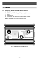
1.0 INTRODUCTION The Check-Line QB-LED is a hand-held, battery-powered stroboscope featuring extremely bright LEDs for the highest light output in its class. Designed for machinery observation, visual inspection and motion analysis, its robust design is suitable for use in the toughest industrial environments. 1.
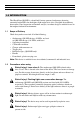
2.0 OVERVIEW 2.1 Connections, controls and settings (QB-LED QBS-LED) (A) (B) (C) (D) (E) CHARGE = charging socket INPUT = input for external trigger /24 V power supply for sensors Display Rotary/push knob Selector switch: OFF, FREQUENCY, BRIGHT, MENU, LASER* *NOTE: LASER Mode only available on QBS-LED model. OFF FREQUENCY (E) BRIGHT INPUT (B) MENU (C) LASER (D) (A) CHARGE PRESS: FLASH ON/OFF Reset 5 sec. Fig.
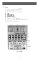
2.2 Display (1) (2) (3) (4) (5) (6) (7) (8) (9) (10) (11) (12) (13) Brightness in μs and/or degrees (BRIGHT) Delay in ms and/or degrees (DELAY) Phase shift (PHASE) Unit of frequency in rpm, Hz and/or FPM Value Multiplier (MULT.) Trigger divider (DIV.) Slow motion (SLOW) Trigger signal edge (TRIG.) Internal/external trigger (INT / EXT) Store / read parameters (MEMORY IN / MEMORY OUT) Pro mode (P) Battery status – full, half full or low (1) (2) (3) (4) (5) (6) (7) (8) (9) (10) (11) (12) (13) Fig.
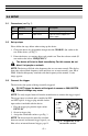
3.0 SETUP 3.1 3.2 Connectors (see Fig. 1) No. Marking Term Description (A) (B) CHARGE Charging Socket Device is charged using a charger INPUT Input socket Input for external tripper/24 V power supply Set-up steps Please follow the steps below when setting up the device: 1. Charge the device by plugginh the charger into the CHARGE (A) socket to the rear of the device (see Fig. 1) 2. Direct the device at a moving object and switch it on.
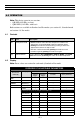
4.0 OPERATION Note: This device comes in two versions. • QB-LED (40 LEDs, no laser) • QBS-LED (118 LEDs, with laser) Both versions are available in Standard and Pro modes (see section 4.3, Standard mode and section 4.4, Pro mode). 4.1 4.2 Controls No. Term Description (D Rotary/Push Knob • Turn the knob to select the value and push to confirm. The adjustment increment depends upon the rotational speed.
4.3 Standard Mode NOTE: Not all of the setting shown in Fig 2 are available in Standard Mode. No. (4) (4) Position of the Selector Switch (E) Adjustable Parameters OFF FREQUENCY — FPM Description Device is switched off Frequency selection; FPM: flashes per minute - Turning the knob while pushing it simultaneously, the adjustment increment is effected in steps of 100. - The flash can be turned off by pushing the knob once and turned on again by pushing the knob once again.
No. Position of the Selector Switch (E) Adjustable Parameters Description (3) MENU PHASE deg: 0…359 Delay setting between the trigger signal and flash (in degrees relative to the frequency Display Phase sift (PHASE in deg) Phase shift setting (in degrees, relative to the frequency) between the trigger signal and flash. This value allows a fixed angle to be set between the trigger signal and flash.
No. Position of the Selector Switch (E) Adjustable Parameters Description (10) MENU INT /EXT Internal /external trigger Display How to select an internal / external trigger 1. Turn the selector switch (E) to the MENU position. 2. Select the INT / EXT parameter by turning the rotary/push knob (D). 3. Push the rotary/push knob (D) to confirm the parameter selection. The display will now show the selection of INT and EXT parameters, the active setting will begin flashing. 4.
4.4 Pro Mode Follow the steps below to access the pro mode: 1. Turn the selector switch (E) from OFF to the required position while simultaneously holding the rotary/push knob (D) until the PRO notification appears in the display. 2. When the Pro mode is activated, a P appears in the bottom right area of the display NOTE: If you have selected settings in Pro Mode and then switch the device off, these settings will ONLY be active when the device is switch back on if pro mode is activated.
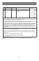
No. Position of the Selector Switch (E) Adjustable Parameters Description (4) MENU rpm / Hz / FPM Unit of frequency selection: Display - rpm: unit for measuring rotational speed - Hz: flash frequency per second - FPM: flashes per minute (6) MENU MULT: x1, x2, x3…/ +1, +2, +3, … respectively.
No. Position of the Selector Switch (E) Adjustable Parameters Description (7) MENU DIV: Pulse divider, max value 255. 1…2550 This function is only possible when the external trigger is selected Display Pulse divider (DIV) The pulse divider can be used to set a value x, by which the external trigger signal is then divided. Example: when scanning a cog wheel, an external trigger (e.g. rotational speed sensor) sends our a signal for each cog scanned.
4.5 Stroboscope QBS-LED NOTE: The model QBS-LED features both a higher number of LEDs (118) as well as a Laser for automatic rotational speed measurement and “Auto-Synching” with target. Risk of injury. The model QBS-LED is fitted with a class 2 laser. The laser beam can damage eyes. For this reason, do not stare directly at the laser beam and never direct it a people or animals. To use the laser, you must first affix a reflective marking onto the object to be measured.
4.6 Operating Modes The following operating modes may be displayed: No. Position of the Selector Switch (E) Adjustable Parameters Description Battery Status Fully charged. Battery Status Half charged. Battery Status Low (symbol will flash). LASER / EXT / SLOW The trigger frequency is below the measurement range LASER / EXT / SLOW The trigger frequency is above the measurement range Display NOTE: The symbol of a parameter that differs from the factory settings will flash during operation.
5.0 DETERMINING THE ROTATIONAL SPEED OF OBJECTS The stroboscope can be used as a digital revolution indicator to determine an object’s actual rotational speed and/or the frequency of cyclical movements. The stroboscope does this by visually “freezing” the object’s movement and then taking a reading of the rotational speed or frequency from the LCD display. As is the case with all stroboscopes, it is vital to ensure that this “frozen” image is not a harmonic of the object’s actual rotational speed.
Which is correct? To determine the fan’s actual rotational speed, one of the ventilator vanes is attached with a marking and the test is repeated. The orientation marking confirms that the images at 3,300, 1,650 and 825 rpm are harmonic multiple images. Three identification marks appear in each of these images. Still images appear at 1,100 rpm and again 550 rpm, each displaying just one mark.
6.0 TECHNICAL DATA General Parameters Number of LEDs QB-LED Both 40 Frequency Range 118 30–300,000 flashed per minute Display LCD, multiline Accuracy ±0.02% (±1 digit/±0.025 µs) Resolution ± 0.1 (30.0 ... 999.9 FPM) ± 1 (1,000 ... 9,999 FPM) ± 10 (10,000 ... 300,000 FPM) External Trigger Input Certifications Flash Parameters 3 - 30 V / max.
7.
8.0 WARRANTY ELECTROMATIC Equipment Co., Inc. (ELECTROMATIC) warrants to the original purchaser that this product is of merchantable quality and confirms in kind and quality with the descriptions and specifications thereof.
NOTES –20 –
CHECK•LINE INSTRUMENTS ® ELECTROMATIC E Q U I P M E N T C O . , I N C . 600 Oakland Ave.