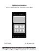
OPERATION MANUAL DAKOTA ULTRASONICS MODEL MX-1 ULTRASONIC THICKNESS GAUGE P/N P-139-0002 Rev 1.
Copyright 2008 Dakota Ultrasonics. All rights reserved. No part of this publication may be reproduced, translated into another language, stored in a retrieval system, or transmitted in any form or by any means; electronic, mechanical, photocopying, recording, or otherwise, without the prior written consent of Dakota Ultrasonics. Every precaution has been taken in the preparation of this publication. Dakota Ultrasonics assumes no responsibility for errors or omissions.
MX-1 Ultrasonic Thickness Gauge CONTENTS I NTRODUCTION 1 OPERATION 3 THE KEYPAD 3 THE DISPLAY 5 THE TRANSDUCER 7 MAKING MEASUREMENTS 8 CONDITION AND PREPARATION OF SURFACES 10 PROBE ZERO 11 CALIBRATION 12 PROGRAMMING THE MX-1’S SOUND VELOCITY 12 TRANSDUCER SELECTION 14 APPENDIX A: PRODUCT SPECIFICATIONS 17 APPENDIX B: APPLICATION NOTES 19 APPENDIX C: SOUND VELOCITIES OF COMMON MATERIALS 23 W ARRANTY I NFORMATION 25 DISCLAIMER Inherent in ultrasonic thickness measurement is the
Dakota Ultrasonics blank page
MX-1 Ultrasonic Thickness Gauge INTRODUCTION The Dakota Ultrasonics model MX-1 is a precision Ultrasonic Micrometer. Based on the same operating principles as SONAR, the MX-1 is capable of measuring the thickness of various materials with accuracy as high as ± 0.001 inches, or ± 0.01 millimeters. The principle advantage of ultrasonic measurement over traditional methods is that ultrasonic measurements can be performed with access to only one side of the material being measured.
Dakota Ultrasonics blank page 2
MX-1 Ultrasonic Thickness Gauge OPERATION The MX-1 interacts with the operator through the membrane keypad and the LCD display. The functions of the various keys on the keypad are detailed below, followed by an explanation of the display and its various symbols. This key is used to turn the MX-1 on and off. When the gauge is turned ON, it will first perform a brief display test by illuminating all of the segments in the display.
Dakota Ultrasonics The PRB-0 key is used to "zero" the MX-1 in much the same way that a mechanical micrometer is zeroed. If the gauge is not zeroed correctly, all of the measurements that the gauge makes may be in error by some fixed value. Refer to page 11 for an explanation of this important procedure. The IN/MM key is used to switch back and forth between English and Metric units.
MX-1 Ultrasonic Thickness Gauge The Display The numeric portion of the display consists of 4 complete digits preceded by a leading "1", and is used to display numeric values, as well as occasional simple words, to indicate the status of various settings. When the MX-1 is displaying thickness measurements, the display will hold the last value measured, until a new measurement is made. Additionally, when the battery voltage is low, the entire display will begin to flash.
Dakota Ultrasonics When the IN symbol is on, the MX-1 is displaying a thickness value in inches. The maximum thickness that can be displayed is 19.999 inches. When the MM symbol is on, the MX-1 is displaying a thickness value in millimeters. If the displayed thickness exceeds 199.99 millimeters, the decimal point will shift automatically to the right, allowing values up to 1999.9 millimeters to be displayed.
MX-1 Ultrasonic Thickness Gauge The Transducer The transducer is the "business end" of the MX-1. It transmits and receives the ultrasonic sound waves which the MX-1 uses to calculate the thickness of the material being measured. The transducer connects to the MX-1 via the attached cable, and two coaxial connectors. When using transducers manufactured by Dakota Ultrasonics, the orientation of the dual coaxial connectors is not critical: either plug may be fitted to either socket in the MX-1.
Dakota Ultrasonics against the material being measured, it is the area directly beneath the center of the wearface that is being measured. This is a top view of a typical transducer. Press against the top with the thumb or index finger to hold the transducer in place. Moderate pressure is sufficient, as it is only necessary to keep the transducer stationary, and the wearface seated flat against the surface of the material being measured.
MX-1 Ultrasonic Thickness Gauge sound velocity (see page 12), the number in the display will indicate the actual thickness of the material directly beneath the transducer. If the Stability Indicator has fewer than five bars darkened, or the numbers on the display seem erratic, first check to make sure that there is an adequate film of couplant beneath the transducer, and that the transducer is seated flat against the material.
Dakota Ultrasonics Condition and Preparation of Surfaces In any ultrasonic measurement scenario, the shape and roughness of the test surface are of paramount importance. Rough, uneven surfaces may limit the penetration of ultrasound through the material, and result in unstable, and therefore unreliable, measurements. The surface being measured should be clean, and free of any small particulate matter, rust, or scale.
MX-1 Ultrasonic Thickness Gauge Probe Zero Setting the Zero Point of the MX-1 is important for the same reason that setting the zero on a mechanical micrometer is important. If the gauge is not "zeroed" correctly, all of the measurements the gauge makes will be in error by some fixed number. When the MX-1 is "zeroed", this fixed error value is measured and automatically corrected for in all subsequent measurements.
Dakota Ultrasonics At this point, the MX-1 has successfully calculated it's internal error factor, and will compensate for this value in any subsequent measurements. When performing a "probe-zero", the MX-1 will always use the sound-velocity value of the built-in probe-disc, even if some other velocity value has been entered for making actual measurements.
MX-1 Ultrasonic Thickness Gauge Programming the MX-1 1) Connect the serial cable (Part No. N-306-0010) to a COM port on a computer and to the RS232 connector located on the bottom of the MX-1. Remove and replace the rubber plug before and after programming. 2) Assuming that DakView2 PC software is installed and running, select the MX-1 icon from the DakView2 gauge selector icons. A window will appear with the title “MX-1 Velocity Upload Utilty”. 3) Under the Preset Velocity heading are two options.
Dakota Ultrasonics TRANSDUCER SELECTION The MX-1 is inherently capable of performing measurements on a wide range of materials, from various metals to glass and plastics. Different types of material, however, will require the use of different transducers. Choosing the correct transducer for a job is critical to being able to easily perform accurate and reliable measurements.
MX-1 Ultrasonic Thickness Gauge strength of the waves, and thus, the MX-1's ability to detect the returning echo. Higher frequency ultrasound is absorbed and scattered more than ultrasound of a lower frequency. While it may seem that using a lower frequency transducer might be better in every instance, low frequencies are less directional than high frequencies.
Dakota Ultrasonics Selection of the proper transducer is often a matter of tradeoffs between various characteristics. It may be necessary to experiment with a variety of transducers in order to find one that works well for a given job. Dakota Ultrasonics can provide assistance in choosing a transducer, and offers a broad selection of transducers for evaluation in specialized applications.
MX-1 Ultrasonic Thickness Gauge APPENDIX A Product Specifications Physical Weight: 10 ounces Size: 2.5W x 4.75H x 1.25D inches (63.5W x 120.7H x 31.8D mm). Operating Temperature: -20 to 120 °F (-20 to 50 °C) Case: Extruded aluminum body / nickel plated aluminum end caps. Keypad Sealed membrane, resistant to water and petroleum products. Power Source Two “AA” size, 1.5 volt alkaline or 1.2 volt NiCad cells. 200 hours typical operating time on alkaline, 120 hours on NiCad. Display Liquid-Crystal-Display, 4.
Dakota Ultrasonics blank page 18
MX-1 Ultrasonic Thickness Gauge APPENDIX B Application Notes • Measuring pipe and tubing When measuring a piece of pipe to determine the thickness of the pipe wall, orientation of the transducers is important. If the diameter of the pipe is larger than approximately 4 inches, measurements should be made with the transducer oriented so that the gap in the wearface is perpendicular (at right angle) to the long axis of the pipe.
Dakota Ultrasonics above this point, the change in sound velocity of the material being measured starts to have a noticeable effect upon ultrasonic measurement. At such elevated temperatures, it is recommended that the user perform a calibration procedure (refer to page 11) on a sample piece of known thickness, which is at or near the temperature of the material to be measured. This will allow the MX-1 to correctly calculate the velocity of sound through the hot material.
MX-1 Ultrasonic Thickness Gauge An additional important consideration when measuring laminates, is that any included air gaps or pockets will cause an early reflection of the ultrasound beam. This effect will be noticed as a sudden decrease in thickness in an otherwise regular surface. While this may impede accurate measurement of total material thickness, it does provide the user with positive indication of air gaps in the laminate.
Dakota Ultrasonics blank page 22
MX-1 Ultrasonic Thickness Gauge APPENDIX C Sound Velocities of some Common Materials Material sound velocity in/us Aluminum Bismuth Brass Cadmium Cast Iron Constantan Copper Epoxy resin German silver G lass, crown G lass,flint Gold Ice Iron Lead Magnesium Mercury Nickel Nylon Paraffin Platinum Plexiglass Polystyrene Porcelain PVC Quartz glass Rubber, vulcanized Silver Steel, common Steel, stainless Stellite Teflon Tin Titanium Tungsten Zinc W a ter m/s 0.250 0.086 0.173 0.109 0.180 0.206 0.184 0.100 0.
Dakota Ultrasonics blank page 24
MX-1 Ultrasonic Thickness Gauge WARRANTY INFORMATION • Warranty Statement • Dakota Ultrasonics warrants the MX-1 against defects in materials and workmanship for a period of five years from receipt by the end user. Additionally, Dakota Ultrasonics warrants transducers and accessories against such defects for a period of 90 days from receipt by the end user.
Dakota Ultrasonics blank page 26
MATERIAL SAFETY DATA SHEET N/A = not applicable or not available (To comply with 29 CFR 1910.1200) SECTION 1 – PRODUCT IDENTIFICATION NFPA Hazardous Materials Identification System (est) Health……………………0 Flammability…………….0 Reactivity………………..0 Product Name: SOUNDSAFE Generic Name: Ultrasonic Couplant Manufacturer: Sonotech, Inc. 774 Marine Dr.