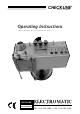
CHECK•LINE ® BY ELECTROMATIC OperatingInstructions Valid as of:01.02.2006•Please keep the manual for future reference! CHECK•LINE ® ELECTROMATIC E INSTRUMENTS Q U I P M E N T C O ., I N C . 600 Oakland Ave., Cedarhurst, NY 11516–U.S.A.
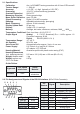
Contents 1 Warranty and Liability ...........................................................................................4 1.1 Notices within the Operating Instructions .........................................................4 1.2 Responsibilities of the Operating Company ......................................................4 1.3 Responsibilities of the Personnel .....................................................................4 1.4 Informal Safety Measures ......................................
1 Warranty and Liability In principle, the supply of the device is subject to our “General Conditions of Sale and Delivery.” These have been provided to the operating company on conclusion of the contract, at the latest. Warranty: - SCHMIDT tension meters are warranted for 12 months. Parts subject to wear, electronic components and measuring springs are not covered by the warranty.
1.4 Informal Safety Measures The Operating Instructions must always be kept on hand where the device is operated. Apart from the Operating Instructions, the generally and locally valid regulations on accident prevention and environmental protection must be provided and complied with. 1.5 Training of the Personnel Only trained and instructed personnel is permitted to work with the device.
2.1 Specifications Calibration: Acc. to SCHMIDT factory procedure with 0.2 mm Ø PA monofil Tension Range: 1 - 500 cN Accuracy: ± 1% FS* ± 1 digit (typically ± 0.5% FS*) Overrange: 10% FS*, without accuracy guarantee Overload Protection: 200% FS* Measuring Principle: Strain gauge bridge Meas. Roller Deflection: max. 0.5 mm Signal Processing: Digital, 12 bit A/D converter Damping: Adjustable electronically (averaging) Meas. Frequency: Approx. 5 kHz internally Display Update Rate: 2x per sec.
2.3 Optional Accessories ET2-CA: Connecting cable for analog signal ET2-CC: Digital connecting cable ET2-P1: “TENSION INSPECT” Software (Win 95 or higher) for viewing and storing the measured data on a PC. 2.3.1 Pin Assignment of the Analog Cable (Option ET2-CA) 9-pin male D-sub connector Pin 9 = analog signal Pin 5 = Ground (GND) 2.4 Delivery Includes Tension meter with 9 V long life battery 1 AC adapter 12 V, 500 mA 1 Pair of scissors 1 Screw driver (1.
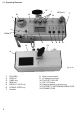
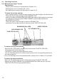
3.1 Operating Elements 12 14 10 1 13 Pos. 2 14 7 9 11 13 Pos. 1 2 3 4 5 6 14 14 8 fig. 3.
3.2 Battery Insertion Before first use of your tension meter, you need to insert the battery. If the –+ –+ symbol is 6 shown on the DISPLAY the battery is low and must be replaced immediately. Operating the tension meter with a low battery may cause measurement errors. To insert the battery: - Open the BATTERY COMPARTMENT which is located on the rear side of the instrument. - Insert a 9 V battery (E block) into the BATTERY COMPARTMENT. Please ensure proper polarity. - Close the BATTERY COMPARTMENT.
3.3 Operating Procedure 3.3.1 Measuring the Upper Tension Requirements: - Tension meter switched on as described in Chapter 3.2.1. - Damping factor set, if necessary (Ch. 3.3.4) - Zero adjustment carried out as described in Chapter 3.2.3.
3.3.2 Measuring the Lower Tension Requirements: - FIXTURE TO DETERMINE BOBIN CASE removed from POSITION 1 and screwed in at POSITION 2. - Tension meter switched on as described in Chapter 3.2.1. - Damping factor set, if necessary (Ch. 3.3.4) - Zero adjustment carried out as described in Chapter 3.2.3. To insert the process material: - Slip the BOBBIN CASE with the full lower-thread bobbin onto the FIXTURE TO DETERMINE BOBIN CASE- Properly insert the LOWER THREAD from the bobbin into the BOBBIN CASE.
3.3.3 Switching on Damping Mode The MST is equipped with an electronic damping which ensures steady readings when tension fluctuates. This is achieved by averaging the measured values at the set update rate. Before switching on the damping mode, it is recommended that you measure the first values without damping enabled. Requirements: - Process material inserted as described in Chapter 3.3. - The DISPLAY has shown the first tension values. To switch on damping: - Press the DAMP key.
3.4 Storing the Tension Values The tension meter features a data logger which stores the following data obtained during a measuring period: Average value, Last value, Maximum value (MAX), Minimum value (MIN), Minimum peak value (MIN PEAK) (lowest single value measured), Maximum peak value (MAX PEAK) (highest single value measured). The measured data remain stored in the MST memory even after the instrument is switched off. Requirements: - Tension meter switched on as described in Chapter 3.2.1.
3.4.1 Recalling the Stored Tension Values (Cont.) - Press the RECALL key. 26 The DISPLAY blinks, showing Peak the maximum peak value of the measuring period, the PEAK indicator and the symbol. - Press the RECALL key. cN 19 the minimum peak value of the measuring The DISPLAY blinks, showing Peak period, the PEAK indicator and the symbol. cN - Press the RECALL key. The tension meter switches back to measuring mode. 3 Mem The DISPLAY shows MEM and the current reading.
3.5 Error Messages Error message 1: EEE . - The DISPLAY shows The upper limit of the tension range was exceeded by more than 10%. Reduce the line tension OR AUTO ZERO is no longer possible. Recalibrate the instrument following the directions in Chapter 3.7.1. Error message 2: - The DISPLAY shows . The lower limit of the tension range was fallen below by more than 10%. Properly insert the process material OR AUTO ZERO is no longer possible. Recalibrate the instrument following the directions in Chapter 3.
3.6 Verification of Measuring Accuracy All tension meters are calibrated with standard materials - such as polyamide monofilament (PA) - according to the SCHMIDT factory procedure. Any difference in process material size and rigidity from the standard material may cause a deviation of the accuracy. In 95% of all industrial applications the SCHMIDT calibration has been proven to provide the best results and is used for comparative purposes.
3.7 Calibration of the MST (Cont.) To calibrate the zero point: - Press the MEM key. As long as the MEM key is depressed, the DISPLAY shows a random decimal value between 500 and 1200 e.g. DELIVERY ROLLER MEASURING ROLLERS 800 . cN This decimal value may vary from instrument to instrument. Write down the decimal value. - Release the MEM key when the value shown on the DISPLAY is fairly stable (the reading might fluctuate greatly). The display 2 shows E - 10 .
3.7 Calibration of the MST (Cont.) b) Press the MEM key 4. As long as the MEM key is depressed, the DISPLAY shows a decimal value which is higher by approx. 800 than the 1800 second decimal value, e.g. . This decimal value may vary from instrument to instrument. Write down the decimal value. - Release the MEM key when the value shown on the DISPLAY is stable (the reading might fluctuate greatly). cN The DISPLAY shows DELIVERY ROLLER MEASURING ROLLERS E - 90 .
3.7.1 Error Messages During Calibration The following error messages might be displayed during the calibration of the tension meter: EEE - The DISPLAY shows . The weight suspended from the process material is too heavy. -EEE . - The DISPLAY shows The weight suspended from the process material is too light. 3.7.2 Restoring the Factory Calibration You can restore the factory calibration any time with the following procedure: Requirement: Tension meter switched off. To restore factory calibration: E -0 .
4 PC Communication (RS-232-C Interface) 4.1 WINDOWS Terminal Program The measured values and the mem- Commands for communication with a PC (polling) ory contents can be transmitted over ASCII the RS-232 interface to a personal Function Description Code computer. You can connect the computer to the connector of the MST Continuous transby using the ET2-CC special cable mission of readContinuous which is available as an accessory. D ings.
5 Service and Maintenance The tension meter is easy to maintain. Depending on operating time and load, the tension meter should be checked according to the locally valid regulations and conditions (as described in Chapter 3.6). The use of other test methods than the procedure described in Chapter 3.6 may cause deviating measuring results. 6 Cleaning i i For cleaning the unit, do not use any AGGRESSIVE SOLVENTS such as trichloroethylene or similar chemicals.
7 Verification of Calibration and Determination of Repair Costs Flow chart for verifying the calibration of used tension meters, incoming and outgoing verification with Inspection Certificate 3.
8 Correspondence Should you have any questions regarding the tension meter or Operating Instructions, or their use, please indicate above all the following details which are given on the ID plate: 1) The tension meter model 2) The serial number 9 Repairs Shipping instructions: We kindly ask for return free of charge for us, if possible by airmail parcel. All occurring charges, if any (such as freight, customs clearance, duty, etc.) will be billed to customer.