
Owner manual


11
4. The Dip Switch Block will be located
at the top of the opening after
removing the Slide Guide Plate.
5.32
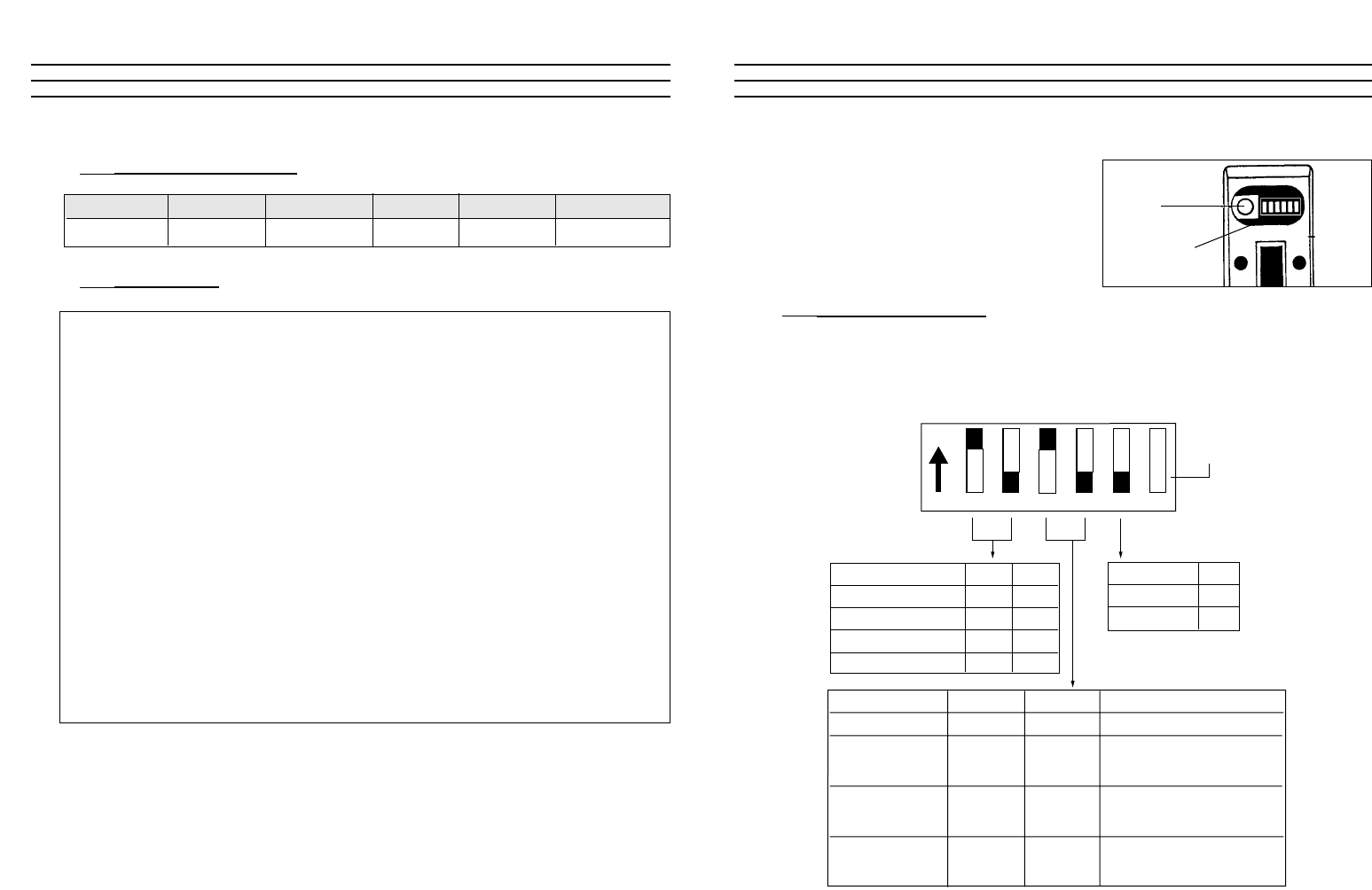
Setting Dip Switches
Using a small slotted screwdriver or other pointed tool, slide each of the five
(5) Dip Switches into the ON (up) or OFF (down) position as indicated in the
illustration below for the desired setting. Dip Switch #6 is not used.
Memory Mode DIP-3 DIP-4 Data Stored in Memory
Standard Memory OFF OFF MIN, MAX, PEAK
Standard Memory
Without Auto– ON ON MIN, MAX, PEAK
Power Off
Extended Memory MIN, MAX, PEAK, AVG, STD. DEV.
(Continuous Mode) ON OFF plus 100 data points
automatically entered
Extended Memory MIN, MAX, AVG, STD. DEV.
(On-Demand Mode) OFF ON plus 100 data points
Display Update Rate DIP-1 DIP-2
0.5 sec OFF OFF
1.0 sec ON OFF
2.0 sec OFF ON
4.0 sec ON ON
Data Output DIP-5
RS-232C OFF
Digimatic ON
123456
ON
DIP Switch #6
(Not Used)
Factory switch:
DO NOT
TOUCH
DIP switches
22
7.51 Signal Characteristics
7.52 Data Format
1 2 3 4 5 6 7 8 9 10 11 12 13
S T A T I S T I C S CR LF
CR LF
U N I T S g CR LF
DATA xx xCRLF
M A X x x x CR LF
M I N x x x CR LF
P EAK x x xCRLF
A V G x x x CR LF
DEV x
● xCRLF
CR LF
D A T A CR LF
1 x x x CR LF
12 xx xCRLF
1 0 0 x x x CR LF
❋❋ END ❋❋ CR LF
Signal Baud Rate Word Length Parity Stop Bits EOL Delimiter
RS-232C 4800 8-bit None 2-bits CR + LF