
Technical data

VSX Architecture and Concepts
Check Point VSX Administration Guide NGX R67 | 28
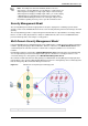
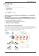
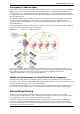
The figure below presents an example of how Virtual Systems connected to a Virtual Switch and a physical
VLAN switch communicate with each other. In this example, a host in VLAN 100 sends data to a server
located in VLAN 200.
Figure 2-12 Routing of virtual traffic between Virtual Systems
1. Traffic from the VLAN 100 host arrives at the VLAN switch, which inserts a VLAN tag and passes it to
the VSX gateway via a VLAN trunk.
2. Based on its VLAN tag, the VSX gateway assigns the traffic to the Virtual System named VS1. VS1
inspects the traffic according to its security policy and forwards the traffic on to the Virtual Switch.
3. VS1 "knows" to forward the traffic to VS2 via the Virtual Switch based on its routing configuration.
4. VS2 inspects the traffic according to its security policy, inserts a VLAN tag, and passes it to back the
VLAN switch.
5. The VLAN switch forwards the traffic to the server located on VLAN 200.
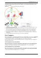
Route Propagation
When a Virtual System is connected to a Virtual Router or to a Virtual Switch, you can choose to propagate
its routing information to adjacent Virtual Devices. This feature enables network nodes located behind
neighboring Virtual Systems to communicate without the need for manual configuration.
Route propagation works by automatically updating virtual device routing tables with routes leading to the
appropriate Virtual Systems.
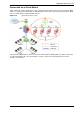
Route Propagation using a Virtual Router
When Virtual Systems are connected to a Virtual Router, VSX propagates routes by automatically adding
entries to the routing table contained in the Virtual Router. Each entry contains a route pointing to the
destination subnet using the Virtual System router-side Warp Interface (wrpj) as the next hop.
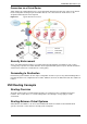
Route Propagation using a Virtual Switch
When Virtual Systems are connected to a Virtual Switch, VSX propagates routes by automatically adding
entries to the routing table in each Virtual System. Each entry contains a route pointing to the destination
subnet using the Virtual System Warp Interface (wrp) IP address.