
Technical data

Introduction to VSX Clusters
Check Point VSX Administration Guide NGX R67 | 92
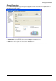
VSX, using the Active/Standby Bridge mode, is incorporated into the distribution layer, enforcing the security
policy. This is illustrated in the following figure:
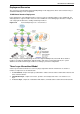
Figure 5-27 Active/Standby bridge mode - core network
The routers direct external, "dirty" traffic to the appropriate Virtual System via a segregated VLAN. Filtered,
"clean" traffic exits the Virtual System via a separate segregated VLAN back to the routers and on to internal
destinations.
Using Virtual Switches in a Cluster
In a VSX cluster, Virtual Switches are also clustered for redundancy. Virtual Switches in the cluster are
defined as active/active.
By means of the ClusterXL Control Protocol (CCP), the physical interface connected to the Virtual Switch is
monitored. In the event of a failover, all Virtual Systems on standby become active, and send gratuitous
ARPs from the warp interface between the Virtual System and the Virtual Switch.
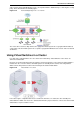
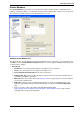
Figure 5-28 Virtual Switches in a cluster
In the above figure, a simplified VSX cluster contains two members, one active, the other standby. The
Virtual Switches within each cluster are active/active. When the physical interface connected to either Virtual
Switch fails to respond, a failover occurs.