
Technical data


VSX Architecture and Concepts
Check Point VSX Administration Guide NGX R67 | 20
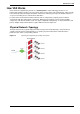
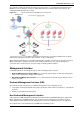
Virtual Switches
By providing layer-2 connectivity, a Virtual Switch connects Virtual Systems and facilitates sharing a
common physical interface without segmenting the existing IP network. As with a physical switch, each
Virtual Switch maintains a forwarding table with a list of MAC addresses and their associated ports.
In contrast to a Virtual Router, when sharing a physical interface via a Virtual Switch there is no need:
To allocate an additional subnet for IP addresses of Virtual Systems connected to the switch.
To manually configure the routing on the routers adjacent to the shared interface.
You can create multiple Virtual Switches in a virtual network topology.
Note - When sharing a physical interface via a Virtual Switch, the IP
addresses for Virtual Systems connected to a Virtual Switch should be
allocated from the same subnet as the shared interface.
If the only function the Virtual Switch performs is to connect Virtual
Systems, then the Virtual Switch can be defined without interfaces
(unless Virtual System load sharing is enabled).
Interfaces
This section describes the various types of interfaces and how they are used in a VSX configuration. The
principal interface types are:
Physical Interface
VLAN interface
Warp Link (including unnumbered interfaces)
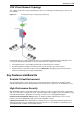
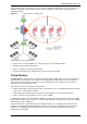
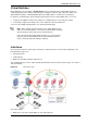
The following figure presents a simple example that illustrates how the various interface types are used in a
VSX environment.
Figure 2-6 VSX interface types
In the above figure:
Warp Links connect the Virtual Switch to each Virtual System.