Smart-1 5 & Smart-1 25 Getting Started Guide Models: S-10, S-21 8 December 2011 704548
© 2011 Check Point Software Technologies Ltd. All rights reserved. This product and related documentation are protected by copyright and distributed under licensing restricting their use, copying, distribution, and decompilation. No part of this product or related documentation may be reproduced in any form or by any means without prior written authorization of Check Point. While every precaution has been taken in the preparation of this book, Check Point assumes no responsibility for errors or omissions.
Important Information Latest Software We recommend that you install the most recent software release to stay up-to-date with the latest functional improvements, stability fixes, security enhancements and protection against new and evolving attacks. Latest Documentation The latest version of this document is at: http://supportcontent.checkpoint.com/documentation_download?ID=12136 For additional technical information, visit the Check Point Support Center (http://supportcenter.checkpoint.com).
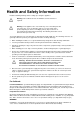
Welcome Health and Safety Information Read the following warnings before setting up or using the appliance. Warning - Do not block air vents. A minimum 1/2-inch clearance is required. Warning - This appliance does not contain any user-serviceable parts. Do not remove any covers or attempt to gain access to the inside of the product. Opening the device or modifying it in any way has the risk of personal injury and will void your warranty. The following instructions are for trained service personnel only.
Welcome Federal Communications Commission (FCC) Statement: Note: This equipment has been tested and found to comply with the limits for a Class A digital device, pursuant to Part 15 of the FCC Rules. These limits are designed to provide reasonable protection against harmful interference when the equipment is operated in a commercial environment.
Contents Important Information .............................................................................................3 Health and Safety Information ...............................................................................4 Introduction .............................................................................................................8 Welcome ............................................................................................................. 8 Smart-1 Overview ..............
Front Panel ....................................................................................................30 LCD Display Screen.......................................................................................30 Hard Disk drives ............................................................................................32 Customer Replaceable Parts ..............................................................................32 Power Supply ........................................................
Chapter 1 Introduction In This Chapter Welcome Smart-1 Overview Shipping Carton Contents Terminology SmartEvent Terminology 8 8 9 9 10 Welcome Thank you for choosing Check Point’s Smart-1. We hope that you will be satisfied with this system and our support services. Check Point products are the most up to date and secure solutions available today.
Shipping Carton Contents Monitoring User Directory Management Portal SmartEvent (IPS Event Analysis, Reporting and Event Correlation) SmartEvent Smart-1 includes SmartEvent, which is made up of IPS Event Analysis, Reporting and Event Correlation. SmartEvent provides centralized reporting and real-time security event correlation and management of your security data. Security teams no longer need to comb through the massive amount of data generated by the devices in their environment.
SmartEvent Terminology SmartDashboard: A SmartConsole GUI application that is used by the system administrator to create and manage the security policy. Management High Availability (HA): Refers to a configuration in which a primary Security Management server has one or more backup secondary Security Management servers which are ready to take over in case of failure of the primary Security Management server.
Safety Instructions Mounting Smart-1 25 in a Rack These instructions show how to install Smart-1 25 in a standard 19 inch rack. Safety Instructions Before installing your appliance in a rack cabinet, review the following guidelines: Make sure that the room air temperature is below 35°C (95°F). Do not block any air vents. Normally, 15 cm (6 in.) of air space in the rear and 5 cm (2 in.) in the front provides proper airflow.
Determining Space and Weight Requirements Determining Space and Weight Requirements Allow sufficient vertical space in the rack for the appliance: Model Height Weight (Kg) Smart-1 25 1U (1.75 inch, 44.5 mm) 13.5 The distance from the center of any hole to the center of the third hole above it is equivalent to 1U. The mounting holes in a standard 19-inch (482.
Rack Mounting Hardware and Required Tools Rack Mounting Hardware and Required Tools Item Description Qty. Use (1) Appliance rail 2 Attaches to the Smart-1 25 appliance. Out-ofthe box it comes combined with the slide. Both appliance rails are identical. Screw (short). 6 Attaches the appliance rail to the appliance RoHS I#6-32*L5-Ni (2) Slide 2 Allows the Smart-1 appliance to slide in and out of the rack for access. Out-of-the box it comes combined with the appliance rail.
Preparing the Appliance Item Description Qty. Use Screw 6 Attaches the bracket ears to the appliance Screw 8 Attaches mounting brackets to the rack vertical rails. Washer 8 Attaches the mounting brackets to the rack vertical rails. Rack Mounting Tools Philips screwdriver. A magnetic head is recommended to hold screws in place and retrieve dropped screws. A powered screwdriver is useful. Pliers. Recommended but not essential.
Attaching the Mounting Brackets to the Slide 4. Attach the appliance rail to the appliance using three screws. One screw at each end, and one screw in one of the two middle holes. 5. Repeat, to attach an appliance rail to the other side of the appliance. Attaching the Appliance Ear Brackets (Optional) The appliance ear brackets are optional. Use them as a Handle, to make it easier to grab the front of appliance and slide it in and out.
Attaching the Slide and Mounting Bracket Assembly to the Rack f) Place a threaded washer on the screw. Leave it slightly loose. (You will tighten it later). 4. Attach a mounting bracket to the back of a slide, using two screws and two threaded washers: a) Open the slide so it is fully extended. b) Position a mounting bracket at the back of the slide so you see four holes straight though. c) Insert one of the screws through the round hole closest to the back of slide, then through the slot in the bracket.
Installing Smart-1 25 in the Rack Installing Smart-1 25 in the Rack 1. Extend the slide fully. 2. Carefully line up the appliance with the rail, and push it about half way in. You will hear a click. 3. To slide the appliance fully into the rack, press the slide latch on the left, then on the right. Take care not to trap a finger. 4. Slide the appliance into the rack.
Chapter 2 Configuring Smart-1 The basic workflow for configuring Smart-1 is: 1. Connect the cables and power on. 2. Perform the initial configuration using the First Time Configuration Wizard. 3. Install the SmartConsole GUI clients. In This Chapter Connecting the Power Cables and Power On Using the First Time Configuration Wizard Installing the SmartConsole GUI Clients Completing the Configuration Advanced Configuration 18 18 22 22 23 Connecting the Power Cables and Power On 1.
Using the First Time Configuration Wizard Starting the First Time Configuration Wizard 1. Connect a standard network cable to the appliance's management interface and to your management network. The management interface is marked Mgmt. This interface is preconfigured with the IP address 192.168.1.1. 2. Connect to the management interface, from a computer on the same network subnet as the management interface. For example: IP address 192.168.1.x and netmask 255.255.255.0. This can be changed in the WebUI.
Using the First Time Configuration Wizard Network Connections Configure the network connections in the Network Connections page. You can change the Management IP address. Connectivity is maintained with an automatically created secondary interface. You can remove this interface after you complete the wizard in the Network > Network Connections page. Routing Table Configure the routing settings on the Routing Table page.
Using the First Time Configuration Wizard Eventia Suite (SmartEvent and Reporter Suite): Configure Smart-1 as a dedicated server for SmartEvent, and no other Software Blade. SmartEvent and Reporter Suite contains SmartReporter Server, SmartEvent Server, and SmartEvent Correlation Unit. Security Management If you choose to install a Security Management server, in the Security Management page: Primary Security Management is the Security Management server that will normally be active.
Installing the SmartConsole GUI Clients You can define a Host according to Hostname or IP address. Enter Any to manage Smart-1 from anywhere. Note - It is not recommended to use the Any value for security reasons. Additional options are available via the WebUI menu, after you complete the First Time Configuration Wizard.
Advanced Configuration Advanced Configuration Advanced configuration can be done using the sysconfig menu which can only be accessed using the command line interface. Note - The sysconfig menu is only available after running the First Time Configuration Wizard in the WebUI. Command line access can be obtained by console connection or through SSH.
Chapter 3 Configuring SmartEvent This section explains how to get up and running with SmartEvent. In This Chapter Preparing SmartEvent on Security Management Server Configuring the SmartEvent Clients 24 24 Preparing SmartEvent on Security Management Server To configure SmartEvent, first establish connectivity between the components. 1. Launch SmartDashboard. 2.
Configuring the SmartEvent Clients Defining the Internal Network for SmartEvent To help SmartEvent Intro determine whether events originated internally or externally, the Internal Network must be defined. Certain network objects are copied from the management server to the SmartEvent Intro server during the initial synchronization and updated afterwards periodically. Define the Internal Network from these objects.
Configuring the SmartEvent Clients If you want to customize the Consolidation session refer to the SmartReporter Administration Guide for your software version on the Check Point Support Center (http://supportcenter.checkpoint.com).
Chapter 4 Smart-1 Hardware This chapter provides instructions for installing and removing hardware components on the Smart-1 appliance.
Smart-1 5 Smart-1 5 This section describes the features and components located on the Smart-1 5 appliance. Front Panel Key Description 1 LCD display screen 2 Screen operation keys 3 Console port - for a serial connection to the appliance using a terminal emulation program such as HyperTerminal 4 USB ports 5 Management configuration port 6 Built-in Ethernet ports (Lan1-Lan4) LCD Display Screen Smart-1 appliances have an LCD screen that lets you do basic management operations.
Smart-1 5 Menu Sub-menu Purpose Set Net mask Set the management interface network mask Set Default GW Set the management interface default gateway Reboot Reboot the appliance System To enter an IP address: Action Press Move to the next digit Move back to the previous digit Approve the change when cursor is located on the last digit Cancel the IP change when cursor is located on the first digit Change current digit or Smart-1 Hardware Page 29
Smart-1 25 Smart-1 25 This section describes the features and components located on the Smart-1 25 appliance. Front Panel Item Description 1 Management configuration port 2 Ethernet connection ports (Lan1 - Lan2) 3 Console RJ-45 port to connect to a computer using a terminal emulation application 4 LCD display screen 5 Lights Out Management (LOM) port 6 USB ports 7 Hard disk drives LCD Display Screen Smart-1 appliances have an LCD screen that lets you do basic management operations.
Smart-1 25 Item Description 1 On/Off indicator LED 2 Network Access LED 3 Disk Access LED 4 LCD Display 5 - Not currently used 6 - Navigate within a menu 7 ? - Not currently used 8 - Not currently used 9 10 11 Enter - Select a menu option or go to the main menu.
Customer Replaceable Parts Action Press Confirm the change Enter when the cursor is located on the last digit Cancel the IP change Esc when the cursor is located on the first digit Change current digit or Hard Disk drives The Smart-1 25 appliance contains two 3-1/2", hot-swappable hard disk drives (RAID 1). This lets you do RAID 1 mirroring across the drives using a dedicated LSI Logic RAID controller.
Hard Disk Drives Hard Disk Drives The Smart-1 25 appliance contains two 3-1/2", hot-swappable hard disk drives (RAID 1). This lets you do RAID 1 mirroring across the drives using a dedicated LSI Logic RAID controller. Use the SecurePlatform raidconfig command to do basic maintenance and monitoring procedures on your Smart-1 RAID array. Usage: raidconfig [status / rebuild /extendstorage / extendfs / alarmon / alarmoff] status - Shows the status of RAID controllers and virtual disks.
Chapter 5 Restoring Factory Defaults You may restore the factory default images on the appliance using the WebUI, a console connection application (such as HyperTerminal) or the LCD panel. Important - Restoring factory default images will delete all information on the appliance including images, backup files, and logs.
Restoring Using the LCD Panel 5. While booting up, the following text appears: 6. When this text appears, there are approximately four seconds to press any key in order to bring up the boot grub menu. Once the boot grub menu is displayed, there will be approximately ten seconds to press any key or the machine will continue booting up. 7. Scroll down the grub menu to highlight Reset to factory defaults. Select the relevant default image version. 8. Press Enter.
Restoring Using the LCD Panel 5. Once you have confirmed the reset, wait for the appliance to restore the factory image. While the appliance is restored to the default image, a Reverting image don't turn off message displays continuously. When the appliance has been restored to its default factory configuration, the appliance reboots and the Initializing message appears.
Chapter 6 Lights Out Management This chapter discusses the Lights-Out Management (LOM) integrated card that is supplied with the Smart-1 25 appliance and basic configuration options.
Introduction Introduction The Check Point Lights Out Management (LOM) is an optional card that you can use with Check Point appliances. You can remotely control Check Point appliances using a dedicated management channel. Lights Out Management also works when the appliance is turned off or not responding. Initial Login 1. Open a web browser and enter the default IP address of the LOM card: 192.168.0.100. The login window appears. 2.
Remotely Controlling the Power of the Appliance 2. Select KVM Console and then Open Console. A new window opens that enables you to remotely control the Smart-1 appliance. Remotely Controlling the Power of the Appliance Using the LOM card, it is possible to remotely switch ON the Smart-1 appliance even if the power is off, switch OFF the appliance, or reset the appliance. Note - The main power switch at the rear of the appliance must be turned ON.
Configuring LOM Keyboard and Mouse To modify a user: 1. 2. 3. 4. Select an existing user from the list and click Modify. The User Modify dialog box appears. Modify the fields as required. To change the password, select Change Password. Click Modify User to apply the changes. To delete a user: 1. Select an existing user from the list and click Delete. A message appears. 2. Click OK.
Chapter 7 Registration and Support In This Chapter Registration Support Where to From Here? 41 41 41 Registration Smart-1 requires a specific license to operate. Obtain a license and register (http://register.checkpoint.com/cpapp). The MAC address required to obtain a license is found on the Information > Appliance Status page of the WebUI. Support For additional technical information about Check Point products, consult the Check Point Support Center (http://supportcenter.checkpoint.com).