
Instructions


63
If the instrument is on emission, you must rst send it a transition 0 -> 1 on the input Rx. This information
commands it to interrupt its transmission. Then, when this is terminated, after sending the end of frame
code, the message command is sent. If the latter is sent too early, it will not be entirely decoded and the
instrument will send the error code ER4.
The minimum time separating 2 read instructions is 1.275s.
The distance mode has priority over the local mode.
The remote control can not start the auto print function.
The remote control can not wake up the instrument which has gone to sleep after 10 minutes of operation
without being manipulated.
There are ve types of remote read possible described in the following paragraphs.
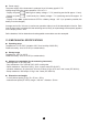
11.1 READ MEASUREMENT
Codes to send to the instrument to get the value of the instantaneous measurement:
- 3F Hexa, 63 Decimal corresponding graphic: ?
For this read instruction to take effect, the instrument must be on Measurement mode or Record mode.
Otherwise, the letter will send back the code Error 1 (ER1) if the instrument is in Read memory mode,
or the code Error 3 (ER3) if the instrument is in Programming mode.
The presentation of the results will be the same as for the local mode (press button).
- From 1 to 5 lines of 38 characters according to the functions of the instrument.
If, during printout of the measurement, the rotary switch is operated or a button is pressed, the printout
of the current message is terminated when the end of frame is sent. Then, the instrument sets itself to
the new function requested.
11.2 READ THE STATE OF THE INSTRUMENT
Codes to send to obtain the output of the state of the instrument regarding the alarms, the condition of
the battery, the type of sensor connected and the position of the rotary switch:
- 26 Hexa, 38 decimal corresponding graphic: &
The reponse to this read instruction is the emission by the instrument on the TxD output, of the codes
corresponding to the different states of the instrument. Presentation on 5 lines each comprising 2 groups
separated by a space:
< Group 1 > < Group 2 >
The rst group contains the function, with 4 characters max:
LO AL for Low alarm
HI AL for High alarm
BAT for the condition of the battery
SEN for the type of probe connected
COMM for the position of the rotary switch