
Instructions


61
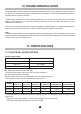
Because of the anisotropy of the measurement probe, during measurement in a given atmosphere, the
aerial must be moved in all planes, along all axes (see gure) :
10. DIGITAL OUTPUT
The C.A 43 has a digital output. this bi-directional interface allows the instrument to communicate with
external peripherals.
To connect the instrument, use the optic bre and the opto-electric adaptor. This transforms the optic
signal into a usable electric signal. The optic bre connects to the COM output of the instrument (see lug
for correct position). The 25 pin opto-electric adaptor connects to the serial port of the computer or the
printer. The mode changer and 25/9 pin reducer could be useful to you as applicable.
This serial output is not perfectly bi-directional as the micro-controllers used do not allow a full duplex link.
The convention adopted for this link only takes into account, on the Rx input, the rst transition 0 -> 1
which is taken as an interruption for the output. At this point, the instrument sets to receiver mode to
decode the message.
Thus, during a transmission, any character sent to input Rx will block it at the end of the current output.
If an ON character is then sent, the output will start again at the point where it was interrupted, in the
same function. But if a code corresponding to another message is sent to the instrument, the output wil
start again in the new function requested. If an OFF code is sent, the instrument denitively exits the
interrupted output mode.
At the end of each transmission, an ASCII 4 code is emitted to indicate the end of the frame. This allows
the peripheral which is connected to know that it can interrupt the transmission.
If the request to interrupt comes before the end of emission character, this command will not be taken
into account until the end of the frame.
C.A 41 + EF1
probe in the
horizontal
plane
In the
vertical
plane