LED PAR 38 TRI-B LED PAR 38 TRI-C Snapshot Use on Dimmer Outdoor Use Sound Activated DMX Master/Slave Autoswitching Power Supply Replaceable Fuse User Serviceable Duty Cycle User Manual 3000 N 29th Ct, Hollywood, FL 33020 U.S.A. (800) 762-1084 – (954) 929-1115 FAX (954) 929-5560 www.chauvetlighting.
TABLE OF CONTENTS 1. BEFORE YOU BEGIN ................................................................................................................................................... 3 WHAT IS INCLUDED ................................................................................................................................................................................ 3 UNPACKING INSTRUCTIONS ........................................................................................................
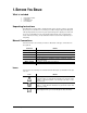
1. BEFORE YOU BEGIN What is included 1 x LED PAR 38 Tri-B/C 1 x Gel Frame 1 x Warranty Card 1 x User Manual Unpacking Instructions Immediately upon receiving a fixture, carefully unpack the carton, check the contents to ensure that all parts are present, and have been received in good condition. Notify the shipper immediately and retain packing material for inspection if any parts appear damaged from shipping or the carton itself shows signs of mishandling.
Safety Instructions Please read these instructions carefully. It includes important information about the installation, usage and maintenance of this product. Please keep this User Manual for future consultation. If you sell the unit to another user, be sure that they also receive this instruction booklet. Always make sure that you are connecting to the proper voltage, and that the line voltage you are connecting to is not higher than that stated on the decal or rear panel of the fixture.
2.
Photometrics The photometric readings have been provided at 1 m, 2 m, and 3 m. Below, you will find a 3-dimensional drawing of the beam and field angles, along with lux and beam diameter for the field and beam angles. The lux measurements provided are maximum outputs at the distances stated. 2.
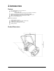
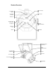
Product Overview Control Panel Power Output (Edison) Fuseholder Power Input (Hardwired) Microphone Attachment Bolt (not meant to be adjusted) Bracket Adjustment Knob Audio Adjustment Knob DMX In DMX Out Hanging/mounting (13 mm hole) Safety attachment point Gel Frame Release Power Input (Hardwired) Gel Frame Power Output Bracket Adjustment Knob Light Output 2.
3. SETUP AC Power This fixture runs on 100~240 VAC, 50/60 Hz. Before powering on the unit, make sure the line voltage to which you are connecting it is within the range of accepted voltages. Always connect the fixture to a switched circuit. Never connect the fixture to a rheostat (variable resistor) or dimmer circuit, even if the rheostat or dimmer channel is used only as a 0 to 100% switch.
Mounting Orientation The LED PAR 38 Tri-B/C may be mounted in any safe position provided there is adequate room for ventilation. Rigging Be sure that the structure can support the weight of the fixture. Please see the “Technical Specifications” section of this manual for a detailed weight listing. Mount the fixture securely. This may be done with a screw, nut and bolt, or a hanging clamp. The hole in each bracket is 13 mm in size. When rigging consider routine maintenance and control panel access.
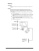
Fixture Linking You will need a serial data link to run light shows of one or more fixtures using a DMX controller or to run synchronized shows on two or more fixtures set to a master/slave operating mode. The combined number of channels required by all the fixtures on a serial data link determines the number of fixtures the data link can support. Fixtures on a serial data link must be daisy chained in one single line.
3-Pin to 5-Pin Conversion Chart If you use a controller with a 5-pin DMX output connector, you will need to use a 5pin to 3-pin adapter. The chart below details a proper cable conversion: 3-PIN TO 5-PIN CONVERSION CHART Conductor 3-Pin Female (Output) 5-Pin Male (Input) Ground/Shield Pin 1 Pin 1 Data ( - ) signal Pin 2 Pin 2 Data ( + ) signal Pin 3 Pin 3 Not used Pin 4 Not used Pin 5 Setting up a DMX Serial Data Link Universal DMX Controller 1.
4. OPERATING INSTRUCTIONS Configuring the Starting Address Each fixture requires a starting address from 1~512. A fixture requiring one or more channels for control begins to read the data on the channel indicated by the starting address. For example, a fixture that uses seven DMX channels and is addressed to start on DMX channel 100, will read data from channels: 100, 101, 102, 103, 104, 105 and 106. Choose the starting addresses for each fixture so that the channels used do not overlap.
Menu Map MAIN FUNCTION SUB-FUNCTION SELECTION SUB-SELECTION INSTRUCTION 7 Color Switching 7 Color fading - 3 Color Switching Select between 2 switching and 2 fading built-in programs 3 Color Fading Use the Audio Adjustment Knob located on the back Select between 2 sound active programs of the fixture 7 Color sound active 3 Color sound active ~ - - Select 3-channel DMX mode (RGB control) ~ - - Select 7-channel DMX mode: RGB, macros, run speed, strobe, automatic/sound, dimmer - Select betwee
Standalone Operation Automatic This fixture has preprogrammed chases. These are accessed via the control panel, and the speed may be adjusted for the chases. Please see the instructions below for further explanation. 1. 2. 3. 4. Press
Fixture Linking In order to use this fixture in a DMX or master/slave operation, you must daisy chain, using DMX cables to link from one fixture to another. In a master/slave operation, the DMX controller is not connected. Additional signal link out DMX controller (only in DMX operation) 4.
DMX Channel Values 7-CH Mode CHANNEL VALUE 1 000 255 Red Dimmer: 0%~100% 2 000 255 Green Dimmer: 0%~100% 3 000 255 Blue Dimmer: 0%~100% 4 000 015 016 255 Color Macros (override CH.1~3) No Function Color Macros 000 255 Speed (CH.
5. APPENDIX DMX Primer There are 512 channels in a DMX connection. Channels may be assigned in any manner. A fixture capable of receiving DMX will require one or a number of sequential channels. The user must assign a starting address on the fixture that indicates the first channel reserved in the controller. There are many different types of DMX controllable fixtures and they all may vary in the total number of channels required. Choosing a start address should be planned in advance.
Setting the Starting Address This DMX mode enables the use of a universal DMX controller device. Each fixture requires a start address from 1~512. A fixture requiring one or more channels for control begins to read the data on the channel indicated by the start address. For example, a fixture that uses six DMX channels and was addressed to start on DMX channel 100, would read data from channels: 100, 101, 102, 103, 104, and 105.
Returns Procedure Returned merchandise must be sent prepaid and in the original packing; call tags will not be issued. Package must be clearly labeled with a Return Merchandize Authorization Number (RMA #). Products returned without the RMA # will be refused. Call CHAUVET and request an RMA # prior to shipping the fixture. Be prepared to provide the model number, serial number and a brief description of the cause for the return.
Technical Specifications WEIGHT & DIMENSIONS Length .......................................................................................................................... 9.3 in (235 mm) Width............................................................................................................................ 8.8 in (223 mm) Height ........................................................................................................................ 11.4 in (290 mm) Weight........................