Series Getting Started User Manual 12 18 37.
Edition Notes Edition Notes This User Manual covers the description, safety precautions, setup, installation, operation, and maintenance for all 3 Modular Video Panels offered by CHAUVET®. This edition was published in January 2012. Trademarks CHAUVET® is a registered trademark of CHAUVET & Sons Inc. (d/b/a CHAUVET® or Chauvet).
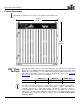
Table of Contents Table of Contents 1. Before You Begin ............................................................................................... 1 What Is Included ............................................................................................................ 1 Unpacking Instructions ................................................................................................... 1 Claims .................................................................................................
Table of Contents 8. Operation .......................................................................................................... 19 Additional Hardware and Software ................................................................................19 About LED Studio .........................................................................................................20 Description ......................................................................................................................
Before You Begin 1. Before You Begin What Is Included Unpacking Instructions Claims Typographic Conventions Icon Meaning • • • • • • Two (2) or Six (6) MVPs (Modular Video Panels) models 12, 18, or 37.5 One Neutrik® etherCON® Signal Cable per MVP™ 0.4 m/15.8 in One Neutrik® powerCON® Power Cable per MVP™ 0.4 m/15.
Before You Begin Safety Notes Please read the following Safety Notes carefully before starting to work with the product. These notes provide important safety information about the installation, usage, and maintenance. This product contains no user-serviceable parts. Any reference to servicing in this User Manual will only apply to properly trained CHAUVET® certified technicians. Do not open the housing or attempt any repairs.
Setup 2. Introduction Product Description Features The MVP™ is a Modular Video Panel. The MVP™ series includes three models: • MVP™ 12 • MVP™ 18 • MVP™ 37.5 Each model is a panel consisting of multiple LED full-color light strips. The number in each model name indicates the pixel pitch (distance, in millimeters, between the LED light strips) of that model. When multiple panels are assembled and connected (signal and power), the entire configuration becomes a modular video wall design.
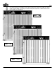
Mounting the MVPs™ Product Overview: MVP™ 12, MVP™ 18, and MVP™ 37.5 Handle Signal Input Signal Output Power Output Underside of MVP™ Panel Ledge Power Input Fast Lock Fast Lock Rigging Plate Rigging Plate Horizontal locking knob LED Strip Rigging Plate Rigging Plate Vertical rigging -4- Vertical rigging MVP™ (12/18/37.5) Series Getting Started User Manual, Rev.
Setup The difference between each MVP™ model is the pixel pitch (space) between the LED strips and the number of pixels (LEDs) on each strip. The basic housing and components are identical. Refer to the previous MVP™ 37.5 illustration. MVP™ 18 MVP™ 12 MVP™ 37.5 MVP™ (12/18/37.5) Series Getting Started User Manual, Rev.
Mounting the MVPs™ Product Dimensions Each MVP™ model in the series has the same outside housing dimensions. 23.6 in (600 mm) 23.6 in (600 mm) MVP™ Pixels Per Panel Although each MVP™ has the same outer dimensions, the LED pixels per panel vary. Each pixel is one SMD5050 LED. The following table provides the pixels per panel in each MVP™. The Series number (i.e., 37.5) indicates the pixel pitch in millimeters between each light strip in that MVP™ model.
Setup 3. Setup AC Power Each MVP™ has an auto-ranging power supply that works with an input voltage range of 100~240 VAC, 50/60 Hz. Make sure that you are connecting the MVPs to the proper voltage, as specified in this User Manual and on the product’s specification sticker. Always connect this product to a protected circuit with an appropriate electrical ground to avoid the risk of electrocution or fire.
Mounting 4. Mounting Orientation Each MVP™ is a solid frame constructed of aluminum alloy and stainless steel. This ensures each panel is stable and easy to install. Each panel also has a convenient built-in handle located on the top, underside, of the panel. This handle enables you to easily pick up and securely hold each panel while mounting and working with the panels. The MVP™ can be assembled to provide any number of modular designs.
Joining Each MVP™ (Creating a Modular Design) 5. Joining Each MVP™ (Creating a Modular Design) Each MVP™ is joined together to create a modular designed video wall. Because the panels are interchangeable, you can create a video wall by joining several of the same model or joining different models to create a larger or more complex video wall.
Joining Each MVP™ (Creating a Modular Design) Use the following instructions to join your panels vertically. Each step corresponds to the number in the diagram. 1. When connecting two (2) panels, pull out the vertical rigging latch making sure it is pushed outward. 2. The fast locks on the lower panel should be pointing up. 3. Align the top and bottom panels exactly on top of each other. Push the vertical rigging inward to fasten.
Joining Each MVP™ (Creating a Modular Design) Horizontally Joining Panels Each MVP™ can be easily joined horizontally using the two horizontal locking knobs on the inside left-hand top and bottom of each panel. Horizontal locking knob Instructions: 1. Align each knob with the corresponding hole on the right-hand outside of the panel to which you are joining. 2. Once aligned, push in and twist clockwise a quarter-turn to lock the two panels horizontally together. 3.
Connecting (Cabling) Each MVP™ 6. Connecting (Cabling) Each MVP™ Testing Signal and Power Connections Each MVP™ has two (2) power supply sockets and two (2) signal sockets. • The Power and Signal IN are located on the upper right-hand corner of each panel. • The Power and Signal OUT are located on the upper left-hand corner of each panel. • The Signal IN and OUT may be used interchangeably. Each MVP™ has LED indicator lights.
Connecting (Cabling) Each MVP™ Connecting the Signal Input The MVP™ video wall system you design can use two basic setup configurations to connect the signal to the video wall: (1) a configuration using 24 or less panels, and (2) a configuration using more than 24 panels. Refer to the following diagrams. See the following section for connecting power to the MVP™ system, and connecting power and signal between joined panels.
Connecting (Cabling) Each MVP™ Connecting Power and Signal Cables The following sections provide information and diagrams on connecting signal and power between panels. One Neutrik® etherCON® signal cable and one Neutrik® powerCON® power cable are included with each MVP™ package—one cable of each kind per MVP™ in the package. These cables are to be used for panel linking only. You are able to purchase additional cables.
Connecting (Cabling) Each MVP™ The following diagram shows an example of a signal connection configuration using more than 24 panels. A video wall design with more than 24 panels requires: • • • Incoming signal connection to the MVP™ Driver. MVP™ Driver connection to the MVP™ Signal Distributor. Signal cable connections as determined by the number of panels in the video wall design. Every group of 24 panels will require another signal cable from the MVP™ Signal Distributor.
Connecting (Cabling) Each MVP™ Connecting the Power Between Joined Panels Power cable panel connections can also use different configurations. The basic configuration to connect the main power supply from one panel to the next is as follows. • • • • The main power is connected to the first panel’s Power Input or Output. A powerCON® cable is then connected to the first panel’s Power Output and connected to the next panel’s Power Input. The connections continue until all panels are connected.
Typical MVP™ Installation 7. Typical MVP™ Installation Because a video wall system can include different components to provide a simple to complex modular wall design, use the following steps as a general guide to get started. Step 1 Open and examine the MVP™ flight case to make sure you have received all products and accessories and that each one is in good condition. Step 2 Apply power and run the self-test for each MVP™ to ensure all LEDs and inside connections in each panel are working (optional).
Typical MVP™ Installation MVP™ Sample Video Wall System Setup The following diagram provides a sample setup for a CHAUVET® MVP™ video wall system. This system setup includes an optional MVP™ 526P Signal Processor for additional video sources, and the MVP™ Signal Distributor to support more than 24 panels. Note that the two-driver setup shown here allows for simultaneous playback of pre-recorded and live content, all directed from a single PC.
Operation 8. Operation Additional Hardware and Software In addition to the panels, you will need other hardware and software to design, build, and operate your MVP™ video wall system. The following table summarizes these additional items—some are required and others are optional. At the bottom, all MVP™ flight case packages are also listed.
Operation About LED Studio Description -20- LED Studio is a powerful and easy-to-learn software application used to design and run the MVP™ Video Wall system. This application is used to play other programs and supports a range of formats (.txt, .doc, images, etc.), as well as video and audio files. Following is some introductory information about this software.
Technical Information 9. Technical Information MVP™ Maintenance To maintain optimum performance and minimize wear, the user should clean this product regularly. Usage and environment are contributing factors in determining the cleaning frequency. As a rule, clean this product at least twice a month. Dust build-up reduces light output performance and can cause overheating. This can lead to reduced light source life and increased mechanical wear.
Technical Information Returns Procedure The user must send the merchandise prepaid, in the original box, and with its original packing and accessories. CHAUVET® will not issue call tags. Call CHAUVET® and request a Return Merchandise Authorization (RMA) number before shipping the product. Be prepared to provide the model number, serial number, and a brief description of the cause(s) for the return. The user must clearly label the package with an RMA number.
10. Technical Specifications MVP™ 12 MVP™ 18 MVP™ 37.5 Light Source Tri-color SMD LED Tri-color SMD LED Tri-color SMD LED Pixels per Panel 48 x 48 (2,304 total) 32 x 32 (1,024 total) 16 x 16 (256 total) 12.5 mm 18.75 mm 37.
CHAUVET® th 5200 NW 108 Avenue Sunrise, FL 33351 (USA) (800) 762-1084 – 954-929-1115 FAX 954-929-5560 www.chauvetlighting.com MVP™ (12/18/37.5) Series Getting Started User Manual, Rev.