RIM-Protocol Converter User Guide Version 1.0 July 2014 While every effort has been made to ensure the accuracy of all information, CPI does not accept liability for any errors or omissions and reserves the right to change information and descriptions of listed services and products. techsupport@chatsworth.com www.chatsworth.com ©2014 Chatsworth Products, Inc. All rights reserved.
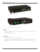
RIM-Protocol Converter User Guide - Version 1.0 Figure 1.1 Protocol Converter (60106-001) Figure 1.2 Dual Port Protocol Converter (60106-002) Introduction This document is the User’s Manual for the Remote Infrastructure Management IRIM) System, RIM-Protocol Converter from Chatsworth Products (CPI). RIM-Protocol Converter User Manual ©2014 Chatsworth Products, Inc. All rights reserved. Legal Information The information contained in this guide is subject to change without notice. Chatsworth Products, Inc.
RIM-Protocol Converter User Guide - Version 1.0 Safety Warnings and Cautions • DO NOT OPEN THE CHASSIS of the RIM-Protocol Converter. There are no user serviceable parts within the RIM-Protocol Converter. Opening or removing covers or other access points may expose you to dangerous shock hazards or other risks. Refer all servicing to qualified service personnel. • Do not spill any liquids on the chassis.
RIM-Protocol Converter User Guide - Version 1.0 Product Warranty Chatsworth Products, Inc. (CPI) guarantees manufactured products and each part or component thereof against all defects in material and/or workmanship. CPI agrees to remedy any manufacturing defect either through replacement or repair at no charge provided that the defective unit is returned, transportation prepaid, to the CPI factory.
RIM-Protocol Converter User Guide - Version 1.
RIM-Protocol Converter User Guide - Version 1.0 6 A Load Firmware & Configuration Files Load Flash Firmware Using MIME Load Flash Firmware Using TFTP Save a Configuration (.cfg) File Load a Configuration (.cfg) File Save a Device Configuration (.xml) File Load a Device Configuration (.xml) File 55 55 57 59 60 61 62 B Troubleshooting 65 C Technical Specifications 67 www.chatsworth.
RIM-Protocol Converter User Guide - Version 1.0 Figures Protocol Converter User Guide Figure 1.1 Protocol Converter (P/N 60106-001) Figure 1.2 Dual Port Protocol Converter (P/N 60106-002) 2 2 1 Product Overview Figure 1.1 Protocol Converter Indicators Figure 1.2 Locations of Terminals 11 12 13 2 Installation Figure 2.1 Protocol Converter with Mounting Brackets Figure 2.2 24VDC Power Supply Connection Figure 2.3 Protocol Converter Ethernet Connection to a PC Using a Crossover Cable Figure 2.
RIM-Protocol Converter User Guide - Version 1.0 8 4 Modbus Communications 51 A Load Firmware & Configuration Files Figure A.1 System Page—Load Flash Firmware Figure A.2 Firmware Load Messages Figure A.3 Identity Link Showing Current Firmware Version Figure A.4 System Page Figure A.5 Bootloader Page Figure A.6 System Page—Download Configuration File Figure A.7 Example Download .cfg Figure A.8 System Page Figure A.9 Device Configuration Link in Top Bar Figure A.10Device Configuration Webpage Figure A.
RIM-Protocol Converter User Guide - Version 1.0 Tables Protocol Converter User Guide 1 Product Overview Table 1.1 LED Indicator Descriptions Table 1.2 Terminal Block Designations Table 1.3 Status Indicator Descriptions 11 12 13 14 2 Installation 15 3 Configuration Table 3.1 Network and Web Configuration Fields Table 3.2 Clock Fields Table 3.3 NTP (Network Time Protocol) Fields Table 3.4 Device Configuration Fields Table 3.5 Modbus Register Configuration Page Options Table 3.
RIM-Protocol Converter User Guide - Version 1.0 10 www.chatsworth.
RIM-Protocol Converter User Guide - Version 1.0 CHAPTER 1 PRODUCT OVERVIEW 1.1. Introduction This manual describes how to install the Remote Infrastructure Management (RIM) System, RIM-Protocol Converter from Chatsworth Products and configure it to communicate using the Modbus, BACnet, and SNMP protocols. IMPORTANT Basic configuration to install the hardware and connect the Protocol Converter to the network is available from CPI.
RIM-Protocol Converter User Guide - Version 1.0 1.2.1 Rear Panel Indicators The back of the Protocol Converter has the following indicators: • Two data transmit/receive indicators to show when data is being transmitted and received through the EIA-485 port (the Dual Port Protocol Converter contains three EIA-485 ports and three sets of data transmit-receive indicators). When data is either being transmitted or received, the status lights will blink.
RIM-Protocol Converter User Guide - Version 1.0 1.2.2 Terminal Block Designations 5 7 6 5 6 7 1 2 3 4 5 6 7 8 Figure 1.2 Locations of Terminals (Dual Port Protocol Converter shown) Item No. Item Description 1 Power 24 VDC/VAC Power Terminal Block 2 Jack Power connector for wall outlet adapter 3 Status Status LED 4 EIA-232 Port DB9 female connector 5 RX TX EIA-485 LED Receive/Transmit status LED. Dual Port Protocol Converter contains two additional sets of LEDs.
RIM-Protocol Converter User Guide - Version 1.0 1.2.3 SW1 Switch Settings Switch Setting SW1-1 Dual Port Protocol Converter only: Duplex (On = 4-wire; Off = 2-wire) SW1-2 EIA-485 Termination (On=100 Ohm termination) Table 1.3 Status Indicator Descriptions 14 www.chatsworth.
RIM-Protocol Converter User Guide - Version 1.0 CHAPTER 2 INSTALLATION 2.1. Tools Required Installation may require a #2 Phillips Screwdriver, wire cutters, wire strippers and a wire crimping tool for 18AWG wire. The Protocol Converter should be shelf or rack-mounted. Rack-mount brackets are included with the Protocol Converter, but rack-mount screws are not included with the Protocol Converter. Contact the rack manufacturer for rack-mount screws. 2.2.
RIM-Protocol Converter User Guide - Version 1.0 2.3. Wire the Protocol Converter If you plan to use the EIA-485 port for Modbus RTU communication, CPI recommends an 18 AWG shielded, twisted-pair stranded copper wire for the connection. CPI recommends no more than 2,000 feet (609.6m) of wire at this specification. 2.3.1 Power Supply & Ground Connections To provide power and ground connections to the Protocol Converter: 1. Connect an 18 AWG ground wire from the ground terminal to a suitable earth ground.
RIM-Protocol Converter User Guide - Version 1.0 2.3.1 RJ45 Ethernet Connection The Protocol Converter has an internal 10/100BaseT Ethernet port used to configure the Protocol Converter. The Ethernet port supports Web browser access, BACnet, Modbus, SNMP, and SMTP (email). Direct Connection To make a direct connection between the Protocol Converter and a computer or laptop using the crossover cable - the blue cable with yellow connectors provided with the device. Figure 2.
RIM-Protocol Converter User Guide - Version 1.0 2.3.3 EIA-232 COM Connection The EIA-232 port can be connected to a PC for IP configuration, firmware downloads, and troubleshooting. NOTE: The EIA-232 is typically only used as a temporary connection. Connect the straight through, 9-pin, serial cable as shown. Figure 2.5 EIA-232 COM Connection 2.3.4 Modbus EIA-485 Connections The Protocol Converter can function as a Modbus Slave or Modbus Master over an EIA-485 hardware connection.
RIM-Protocol Converter User Guide - Version 1.0 CHAPTER 3 CONFIGURATION The Protocol Converter allows you to view and configure slave devices and slave registers over the Web. To access the Web interface, you must first set up the Protocol Converter to communicate over the Internet. To set the IP address, see “Configure Communications” on page 19. Follow the order of the sections in this chapter to completely configure the slave devices, registers, and the Protocol Converter. 3.1.
RIM-Protocol Converter User Guide - Version 1.0 3.1.1 Set the IP Address Using a Web Browser Unless you are familiar with setting the IP address, consult your IT department before attempting this procedure. To use a Web browser to set the Protocol Converter's IP address: 1. Plug a crossover network cable into the laptop or workstation that will be used to configure the Protocol Converter. 2. Write down the computer's current IP address and Subnet Mask.
RIM-Protocol Converter User Guide - Version 1.0 7. Select the Configuration link from the top bar, then select the Network and Web link from the Configuration menu. Figure 3.2 Protocol Converter Configuration, Network and Web Screen 8. On the Network and Web page, change the IP address, Subnet Mask (Net Mask), and Default Gateway (Def Route) to one provided by your network administrator. Figure 3.3 Change the IP Address Through the Web Interface 9. Press the Submit Changes button.
RIM-Protocol Converter User Guide - Version 1.0 3.1.2 Set the IP Address Using an EIA-232 Connection To use the EIA-232 interface to set the Protocol Converter’s IP address: 1. Connect the EIA-232 port on the Protocol Converter to a terminal or PC running terminal emulation software (HyperTerminal) with a 9-pin, male-female, straight-through serial cable. 2. Set the appropriate communication port to 9600 baud, no parity, 8 data bits, 1 stop bit, (9600/N/8/1), and no software or hardware flow command. 3.
RIM-Protocol Converter User Guide - Version 1.0 3.2 Log In to the Protocol Converter Once the IP address for the Protocol Converter has been set as described in 3.1., “Configure Communications” on page 19, you can log in to the Protocol Converter: Open a Web browser and type the Protocol Converter’s IP address (default is 10.0.0.188) into the location bar. When prompted, enter the Protocol Converter user name (default is cpi). Figure 3.
RIM-Protocol Converter User Guide - Version 1.0 Once setup, each device’s status is color coded. Figure 3.6 Protocol Converter Color Codes Note: The color codes are also available in the Help section of the Protocol Converter interface. Click on an individual device number to view individual information being polled from that device to the Protocol Converter. Device #1: I/O Module Figure 3.7 Register Status Example 24 www.chatsworth.
RIM-Protocol Converter User Guide - Version 1.0 3.3 Configure Network and Web Properties Use the Configuration section of the Protocol Converter’s web interface to configure basic device functionality. The Network and Web link displays the MAC address and allows you to fill in the IP Address, Net Mask, Default Router (Default Gateway), Passwords, and Refresh rate. In the user interface, go to Configuration>Network and Web. Edit the fields appropriately. Figure 3.
RIM-Protocol Converter User Guide - Version 1.0 Option Description Web Password Read/Write The Protocol Converter can be configured with two passwords - the read/ write password allows users to access the web interface and to edit all settings. Specify an alphanumeric value up to 16 characters. Web Refresh Rate This integer value represents how long the system waits until it updates the Web interface with current data.
RIM-Protocol Converter User Guide - Version 1.0 3.4 Set and Synchronize the Clock When you’re configuring the Protocol Converter, be sure to set and synchronize the Protocol Converter’s clock. This ensures all time-stamped events are accurate. Do this on the Configuration>Clock screen. Figure 3.9 Clock Configuration Page Option Description Date Enter the date in mm/dd/yy format. Time Enter the time in hh:mm:ss format (24-hour clock). Table 3.2 Clock Fields Chatsworth Products, Inc.
RIM-Protocol Converter User Guide - Version 1.0 3.4.1 Network Time Protocol (NTP) Network Time Protocol (NTP) is used to synchronize clocks of computer systems. NTP synchronizes the time of a computer or device (the Protocol Converter) to another computer or referenced time source. NTP maintains a high level of accuracy and reliability in time stamped events. NTP is found on the Configuration>Network Time Protocol screen. Figure 3.
RIM-Protocol Converter User Guide - Version 1.0 3.5 Configure Slave Devices Once the basic functionality of the Protocol Converter has been configured, you’re ready to configure slave devices. You can configure up to 32 slave devices to the Protocol Converter. 1. From the top navigation bar on the Protocol Converter’s home page, click the Device Configuration link. The Device Configuration page is divided into four subpages - eight slave devices can be configured on each page.
RIM-Protocol Converter User Guide - Version 1.0 Option Description Modbus Slave Address / Unit Identifier IP Address A numeric value that indicates the slave address for Modbus communications. Type an integer ranging from 1 to 254. If Modbus communications will not be used, leave this value at 0. Enter the IP address of the device being polled for Modbus TCP, SNMP, or BACnet/IP slave data. Device Name Enter a descriptive label to identify the slave device you are polling.
RIM-Protocol Converter User Guide - Version 1.0 3.6 Configure Device Registers Once the desired slave devices have been configured on the Protocol Converter, you can program registers to those slave devices for the proper information to be polled. First, you can select whether or not to enable write operations to the slave devices, then you can program the registers. NOTE: You can also delete the Protocol Converter’s entire register set.
RIM-Protocol Converter User Guide - Version 1.0 3.6.2 Register Configuration Web Pages Access the Register Configuration page by clicking on the Registers link in the menu bar. 1. Click on the register number to configure individual registers. Figure 3.12 Register Configuration Page The configuration page for that register displays. Notice that the Unit number corresponds to the Device number listed on the Register Link page. 2. Enter the necessary information for the register type you are configuring.
RIM-Protocol Converter User Guide - Version 1.0 3.6.3 Modbus Register Configuration If you are configuring a Modbus device, the register configuration page looks like this: Figure 3.13 Modbus Register Configuration 1. Type an appropriate value in each field, or choose the value from the drop-down. Option Description Unit This is the unit number of the register you’re configuring. Modbus Register The Modbus register to be polled by the Protocol Converter to that specific slave.
RIM-Protocol Converter User Guide - Version 1.0 Option Description Bitflag The proper bit flag to be used for this particular register. Choose values from :00 to :15. Modbus Word Order Determines the way the register is read by the Protocol Converter. Choose from Big-Endian (Left to Right) or LittleEndian (Right to Left). Gain The gain value of the raw data being received. Set this value only if necessary. Offset The offset value to the calculated reading for the register.
RIM-Protocol Converter User Guide - Version 1.0 Option Description BACnet Instance The number used by a BACnet master for polling data from the Protocol Converter. Possible values include Analog Instance (AI) or Binary Instance (BI). BACnet Engineering Units In the BACnet ASHRAE standard, numbers correlate with units of measure. Refer to the BACnet ASHRAE standard for more information.
RIM-Protocol Converter User Guide - Version 1.0 4. Write a specific value to a Modbus register by clicking the Manual Preset Single Register link on the individual register pages. This option is only available for writeable Modbus registers (40001 and above). Figure 3.15 Modbus Manual Preset Single Register Link When you click this link, the Modbus Preset Single Register webpage displays. Figure 3.16 Modbus Preset Single Register Webpage 5.
RIM-Protocol Converter User Guide - Version 1.0 3.6.4 SNMP Register Configuration If you are configuring an SNMP device, the register configuration page looks like this: Figure 3.17 SNMP Register Configuration 1. Type an appropriate value in each field, or choose the value from the drop-down. Option Description SNMP Get OID The OID (object identifier) the Protocol Converter uses to gather the correct integer data from the SNMP device being polled. OID Type The object identifier type.
RIM-Protocol Converter User Guide - Version 1.0 Option Description Indicates the value that, when reached or exceeded, causes the Protocol Converter to trigger an alarm. Threshold 1 Specify if the alarm should occur when the reading is less than (<), Equal to (=) or greater than (>) the specified threshold value. Indicates the value that, when reached or exceeded, causes the Protocol Converter to trigger an alarm.
RIM-Protocol Converter User Guide - Version 1.0 You can also click the First, <
RIM-Protocol Converter User Guide - Version 1.0 3.6.5 BACnet Register Configuration If you are configuring a BACnet device, the register configuration page looks like this: Figure 3.21 BACnet Register Configuration 1. Type an appropriate value in each field, or choose the value from the drop-down. Option Description BACnet Instance The Instance number used by the Protocol Converter to poll the desired data from that BACnet device.
RIM-Protocol Converter User Guide - Version 1.0 Option Description HTML Display This option allows you to choose how the value is displayed on the register page. Choose from Integer (whole number) or Float (a number plus a decimal). Indicates the value that, when reached or exceeded, causes the Protocol Converter to trigger an alarm. Threshold 1 Specify if the alarm should occur when the reading is less than (<), Equal to (=) or greater than (>) the specified threshold value.
RIM-Protocol Converter User Guide - Version 1.0 3. Once the changes have been accepted, click on Next>> link at the bottom of the page. You can also click the First, <
RIM-Protocol Converter User Guide - Version 1.0 3.6.6 Delete All Registers If you need to reconfigure the Protocol Converter for a new application, you can delete the entire register set. IMPORTANT: Consider the Delete All Registers option carefully and use it with caution. You should use this option only if you need to reconfigure the Protocol Converter for a new application. To delete all programmed registers: 1. In the user interface, go to Configuration>System. The System web page displays.
RIM-Protocol Converter User Guide - Version 1.0 3.7 Set Communication Protocol Options Set the Modbus, BACnet, or SNMP protocols as described in the following sections. 3.7.1 Modbus/EIA-485 Port Configuration To configure the Modbus/EIA-485 port, use the top navigation bar to access the Configuration screens. Select the EIA-485/Modbus/BACnet-MSTP Ports option and configure the fields accordingly. Figure 3.
RIM-Protocol Converter User Guide - Version 1.0 Option Description Max. EIA-485 Device Response Time This setting determines the allowable response time, in seconds, from devices before the Protocol Converter times out. Set a value in the range of 0.3 to 9.9 seconds. If the Protocol Converter times out, an offline alarm will be triggered and the device’s status color will change on the Protocol Converter’s home page.
RIM-Protocol Converter User Guide - Version 1.0 3.7.2 BACnet Server Configuration From the Configuration page, click the Bacnet link to configure the BACnet Server. 3.27 BACnet Server Configuration Enter the following settings for the BACnet server: Option Description Device ID A numeric value that uniquely identifies each BACnet Device on the network. Device Name Designate a name for the device, up to 40 characters in length.
RIM-Protocol Converter User Guide - Version 1.0 Option Description This is the user datagram protocol port, which is used by applications to send messages to a device (in this case, the Protocol Converter). UDP Port Enter 0 to specify port 47808 as the UDP port. If another port is specified by your application, enter a new port number in this field. Default setting: 0 (47808) BACnet-MS/TP Port3 Max Master Set the slave address, 1/127. 0 = slave only.
RIM-Protocol Converter User Guide - Version 1.0 3.7.3 SNMP The SNMP Server configuration page allows you to set the System Name (displayed on the home page), System Contact, and System Location. You can also set up communities that allow multiple SNMP systems to access the Protocol Converter. Note: To set up communities, you must know the IP address of the SNMP Management System and the Community String. If necessary, contact your Technical Support department to obtain the IP Address and Community String.
RIM-Protocol Converter User Guide - Version 1.0 3.7.3 SNMP (Email) Use the SMTP configuration section to set up the Protocol Converter’s communication to email recipients. The Protocol Converter can send email to up to four recipients. Recipients can include an exchange server using a distribution list, an email account, or a cell phone. The Protocol Converter can also communicate via ESMTP (Authenticated) to mail servers requiring a login name and password.
RIM-Protocol Converter User Guide - Version 1.0 Option Description Mail Sender Address The email address used by the Protocol Converter to communicate to the mail server. Mail Subject Description to be displayed on the email notification subject line. Mail Recipient (1-4) The address for an email account, cell phone, or distribution list. • None is used for no username or password being required. • Plain is used for standard Username and password authentication.
RIM-Protocol Converter User Guide - Version 1.0 CHAPTER 4 MODBUS COMMUNICATIONS This chapter describes the Modbus communication protocol as supported by the Protocol Converter. The content includes details and information on how to configure the Protocol Converter for communications via Modbus network. 4.1. Implementation Basics The Protocol Converter is capable of communicating via the half-duplex EIA-485 serial communication standard.
RIM-Protocol Converter User Guide - Version 1.0 4.1.1.2 Function Field The function field is one byte in length and tells the Protocol Converter which function to perform. The supported functions are 03 (Read 4xxxx output registers). 4.1.1.3 Data Field The data field of the request is a variable length depending on the function. The data fields for the Protocol Converter are 16-bit registers, transmitted high order byte first (big-endian) 4.1.1.
RIM-Protocol Converter User Guide - Version 1.0 Read Registers Request Packet Read Registers Response Packet Slave Address (1 byte) Slave Address (1 byte) 03 (Function code) (1 byte) 03 (Function code) (1 byte) Start Register (2 bytes) Byte count (1 byte) # of registers to read (2 bytes) First register (2 bytes) CRC Checksum (2 bytes) Second register (2 bytes) … CRC Checksum (2 bytes) Table 4.
RIM-Protocol Converter User Guide - Version 1.0 54 www.chatsworth.
RIM-Protocol Converter User Guide - Version 1.0 APPENDIX A LOAD FIRMWARE & CONFIGURATION FILES You can perform the following firmware and configuration operations for the Protocol Converter: • Load different firmware to the Protocol Converter. CPI occasionally posts updates for the firmware to add enhancement or fix errors. Firmware updates are available on the CPI website at http://www.chatsworth.com/support-and-downloads/downloads/software/.
RIM-Protocol Converter User Guide - Version 1.0 The System webpage displays. Figure A.1 System Page—Load Flash Firmware 4. Click the Browse button. 5. Locate and choose the firmware file (.bin) that you saved from the CPI website. 6. Click the Upload button. While the firmware file loads, you’ll see the following confirmation message: Figure A.2 Firmware Load Messages When the file is loaded, the Protocol Converter reboots itself. The reboot process takes approximately 60 seconds.
RIM-Protocol Converter User Guide - Version 1.0 A.2. Load Flash Firmware Using TFTP Loading firmware via TFTP (trivial file transfer protocol) requires a TFTP client. It may be possible to download a free license TFTP client from the internet. Consult your IT department to determine a compatible client program. Before updating the firmware, the firmware flash application must be exited and then erased as follows: 1.
RIM-Protocol Converter User Guide - Version 1.0 6. Send or PUT the firmware file to the Protocol Converter. It may take ~10 seconds for the firmware upload to begin. This will put the new firmware into effect. 7. After one minute, refresh the Protocol Converter webpage. Notice that the Flash Application field now contains the latest firmware. Click the “Start Application” button to reboot the unit. 58 www.chatsworth.
RIM-Protocol Converter User Guide - Version 1.0 A.3. Save a Configuration (.cfg) File If you would like to make a backup of your custom configuration or copy the same configuration to several Protocol Converters rather than changing the settings manually on each unit, save the configuration (.cfg) file. To save the .cfg file: 1. In the user interface, go to Configuration>System. Click the Download Configuration File .cfg link. The System webpage displays. Figure A.
RIM-Protocol Converter User Guide - Version 1.0 A.4. Load a Configuration (.cfg) File Once you have saved a configuration file as described in A.3., “Save a Configuration (.cfg) File” on page 59, you can load that file to the same Protocol Converter or other Protocol Converters. To load a configuration file (.cfg) to the Protocol Converter: 1. Ensure that the .cfg file you want to load is on a local drive. 2. On the Protocol Converter interface, go to Configuration>System. Figure A.8 System Page 3.
RIM-Protocol Converter User Guide - Version 1.0 A.5. Save a Device Configuration (.xml) File When you have a configured a specific device using the Protocol Converter’s interface, you can save that device configuration and load it to another device of the same type. This procedure may not work in all cases; some manufacturers use the same register set across different models of the same type of device, and others do not. To save a device configuration: 1.
RIM-Protocol Converter User Guide - Version 1.0 A.6. Load a Device Configuration (.xml) File An .xml file that you have saved using the Protocol Converter’s user interface can be loaded to another device. This procedure may not work in all cases; some manufacturers use the same register set across different models of the same type of device, and others do not. To load an .xml file to a device: 1. Click the Device Configuration link in the top bar. Figure A.11 Device Configuration Link 2.
RIM-Protocol Converter User Guide - Version 1.0 5. Click Upload. One of three message displays: • XML file upload complete. • XML file cannot be upload - index base was not specified. If this occurs, retry the operation and specify a register number in the Index Base box. • File has been uploaded - but type is unknown. Proceed to step 6. 6.
RIM-Protocol Converter User Guide - Version 1.0 9. Revert to the preset registers or delete all register information as follows: • To revert to the preset values, indicate a Start Index number. This is the number of the register at which you want to begin the preset operation. If you choose to preset the register values, the following message displays when the operation is complete: 8036 registers preset at index 1 • If you choose Delete Device/Registers, all device information will be deleted.
RIM-Protocol Converter User Guide - Version 1.0 APPENDIX B TROUBLESHOOTING Problem Action Control Panel will not Power Up 1) Check with a DVM (Digital Volt Meter) for AC or DC input power on the lower left hand terminal block on the Protocol Converter. If no voltage is present at terminal block, check the circuit breaker or power supply that powers the Protocol Converter. Unable to see the web page 2) If voltage is present contact CPI for further troubleshooting.
RIM-Protocol Converter User Guide - Version 1.0 Problem Action Slave units are showing loss of communication. 1) Check the Device Configuration in the Protocol Converter and make sure the proper addressing is assigned. a) Modbus-RTU/485: The device address is set to the proper RTU address and the 485 communications line is wired properly. b) Modbus TCP/IP: The Proper device address and IP address has been assigned. Modbus TCP/IPcommunications requires port 502 of that IP address to be enabled/open.
RIM-Protocol Converter User Guide - Version 1.0 APPENDIX C TECHNICAL SPECIFICATIONS Table C.1 Technical Specifications Power 24VAC @ 600mA max, 50/60Hz, 24VDC @ 600mA max. Communications Ports Ethernet 10/100 BASE-T, RJ45 connector; 500VAC RMS isolation EIA-232 DB9 female connector; 9600 baud; No parity, 8 data bits, 1 stop bit 1200, 2400, 9600 or 19200 baud (selectable); Parity: none, EIA-485 (Dual Port Protocol even or odd, 8 data bits, 1 stop bit.
RIM-Protocol Converter User Guide - Version 1.0 Table C.1 Technical Specifications Indicators Status 1 Red: flashing=boot-up sequence; solid=alarm condition EIA-485 Transmit and Receive 1 Green Transmit; 1 Green Receive (additional LEDs for Dual Port Protocol Converter) Operating Environment 68 Temperature 32ºF to 122ºF (0ºC to 50ºC) Humidity 5% to 95% RH (non-condensing) Altitude 15,000ft (4572m) max. Storage Temperature –4ºF to 185ºF (–20ºC to 85ºC) Mounting Desktop or 19"W EIA (482.