F-‐Series TeraFrame® F-Series TeraFrame® Gen 3 Cabinet System User’s Manual ©2013 Chatsworth Products, Inc. All rights reserved. CPI, CPI Passive Cooling, MegaFrame, Saf-T-Grip, Seismic Frame, SlimFrame, TeraFrame, GlobalFrame, Cube-iT Plus, Evolution, OnTrac, QuadraRack and Velocity are federally registered trademarks of Chatsworth Products, Inc. eConnect and Simply Efficient are trademarks of Chatsworth Products, Inc. All other trademarks belong to their respective companies.Rev.
Contents F-‐Series TeraFrame Gen 3 Cabinet Overview ...................................................................................... 3 Introduction to the F-‐Series TeraFrame Gen 3 Cabinet .......................................................................... 3 Safety Information ..................................................................................................................................
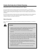
F-‐Series TeraFrame Gen 3 Cabinet Overview Introduction to the F-‐Series TeraFrame Gen 3 Cabinet The F-‐Series TeraFrame® Gen 3 Cabinet System from Chatsworth Products, Inc. (CPI) has been developed to meet a wide range of application needs.
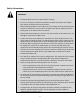
Safety Information WARNINGS: • Unload equipment from the cabinet before moving it. • Two or more cabinets can be bayed together (coupled) to enhance their stability. Each cabinet should be anchored to the floor. • Before loading equipment in the cabinet, be sure to adjust and lock the leveling feet to level the cabinet.
Intended Use Keep a printed copy of the Preface of this User’s Manual in or near the cabinet. • Install the cabinet only in a Restricted Access Location, such as a data center. • Use indoors only, in environmentally controlled areas; do not use outdoors, in harsh environments, or in air-‐handling spaces.
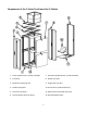
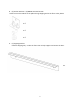
Components of the F-‐Series TeraFrame Gen 3 Cabinet 1. Frame (6-‐Slide shown, 4-‐Slide available) 7. Side panel (6-‐Slide Shown, 4-‐Slide available) 2. Front door 8. Double rear door 3. Equipment mounting rails 9. Single solid rear door 4. Standard top panel 10.
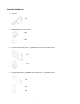
Included Hardware 1. (2) Keys x 2 2. (50) M6 Cage Nuts and Screws x 50 x 50 3. (2) Standard PDU Brackets + (4) M6x16 Screw and Front Mount Nut x 2 x 4 4.
5. (1) Ground Terminal Block + (2) M5x16 Bolt + (2) M5 Hex Nut + Antioxidant Compound x 1 x 2 x 2 6. (1) Label Holder x 1 7.
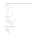
8. (4) Anchor Brackets + (4) M8x20 Hex Head Screws Used to secure the cabinet to the pallet during shipping and to the floor at the jobsite. x 4 x 4 x 4 9.
Getting Started Tools Required 1. Utility Knife a. For removing stretch wrap from around cabinet 2. 13 mm Socket Wrench a. For removing shipping brackets securing cabinet to pallet b. For adjusting equipment mounting rail c. For installing baying brackets 3. 13 mm Open End Wrench a. For adjusting leveling feet 4.
Inspect the cabinet for damage. If any damage to the cabinet is observed, contact your distributor or CPI Customer Service. 1. Carefully remove the plastic wrap surrounding the cabinet using a utility knife. Be careful not to allow the knife to contact the cabinet as this may damage the unit. 2.
Installation Moving the cabinet CAUTION: The F-‐Series TeraFrame Gen 3 Cabinet ships on casters. Move the cabinet by pushing on the front or the rear of the cabinet. Do not push the cabinet from the sides. The TeraFrame cabinet has been provided with four (4) casters to allow the cabinet to be rolled into position.
Anchor Bracket The mounting locations for the anchor brackets are shown in the figure below. If used as part of an aisle containment solution, inistall the Floor Seal Kits (P/Ns 39208-‐XXX and 39209-‐XXX) before attaching the anchor brackets.
Baying cabinets together F-‐Series TeraFrame Gen 3 Cabinets can be bayed (fastened) together with solid side panels in place, with a shared solid or brush side panel between cabinets, or with no side panels, depending on installation requirements. Cabinets must be the same height and depth. 1.
Configuring the cabinet The F-‐Series TeraFrame Gen 3 Cabinet can easily be configured for a variety of applications. Not only can the standard cabinet components be adjusted or removed, but a broad range of accessories can be installed to create a cabinet solution that meets all the needs of your installation requirements.
Installing the Front Door: 1. Hold the door so that it is perpendicular to the cabinet and align the hinge pins on the door with the hinge barrels on the cabinet. The door is perpendicular to the cabinet when it is parallel with the side of the cabinet. 2. Lift the door and move it toward the hinges.
Removing and Installing the Rear Doors Removing the Rear Doors: 1. With the doors closed, lift and remove the hinge pins from both the upper and lower hinges on the door that you want to remove. 2. Partially open the door, but not as far as 90 degrees. 3. Disconnect the ground wire. 4.
Removing and Installing the Top Panel Removing the One-‐Piece Top Panel: 1. Remove two (2) shipping brackets on top of cabinet using 13mm socket wrench. 2. Open the rear door(s) of the cabinet. Remove grounding wire from the top panel (item 1 in image next page). 3.
Removing the Two-‐Piece Top Panel: 1. Open the rear door(s) of the cabinet. Remove grounding wire from the top panel. 2. Depress and hold the two (2) spring retainers that hold the rear top panel to the frame. 3. Push up on the rear top panel and remove. 4.
Installing the Two-‐Piece Top Panel: 1. Align the front edge of the front top panel with the frame. 2. Lower the front top panel, sliding it forward to make contact with the front of the frame. 3. Install two (2) screws to secure front top panel to the frame slides. 4.
Removing and Installing the Side Panels Removing the Side Panels on 6-‐Slide Cabinet: 1. Unlock the side panel latch with the key (if necessary). 2. Retract the side panel latch by pulling down and allow the side panel to tilt away from the cabinet. 3. Disconnect the ground wire. 4.
Removing the Side Panels on 4-‐Slide Cabinet: 1. Unlock the top side panel latch with the key (if necessary). 2. Retract the top side panel latch by pulling down and allowing it to tilt away from the cabinet. 3. Disconnect the ground wire from the top side panel. 4. Lift up on the side panel and remove it from the cabinet. 5.
4. Align the top side panel on the bottom side panel and slip the side panel into the side of the frame. 5. Connect the ground wire. 6. Rotate the top side panel up to meet the frame and slightly lift to engage the upper half of the two side panel catches on both ends of the frame.
Adjusting the Equipment Rails 1. Use a 13 mm socket wrench to loosen (but do not remove) the nuts securing the equipment rail to the frame in three (3) locations on 6-‐Slide cabinet or two (2) locations on 4-‐Slide cabinet. 2. Move the equipment rail forward or backward to the desired location. 3.
Installing Equipment The F-‐Series TeraFrame Gen 3 Cabinet supports all manufacturers’ equipment that conforms to the EIA/ECA-‐310E standard. Most equipment attaches directly to the equipment mounting rails; however, some manufacturers may provide brackets or slide assemblies that require additional installation.
Accessories Cable Management Finger Cable Manager no Cover For 23.6” (600 mm) wide cabinets Fingers, attaches to equipment rail (Fits other width cabinets also.) Finger Cable Manager with Cover For 27.6” (700 mm) wide cabinets Fingers, Attaches to equipment rail Finger Cable Manager with Cover For 31.
Cable Management (cont’d) Cable Lashing Bracket, 4-‐Slide Cabinet One (1) full-‐height panel Attaches to the cabinet frame Ring Cable Manager, 4-‐Slide Cabinet For 23.6” (600 mm) wide cabinets One (1) full-‐height section Ring Cable Manager, 4-‐Slide Cabinet For 27.
Power Management One set of standard PDU brackets is included with the F-‐Series TeraFrame Gen 3 Cabinet. Additional PDU brackets are available as well as a wide range of power strips and PDU’s, including monitored and switched versions.
Thermal Management Vertical Exhaust Duct 600 -‐ 39177-‐X00 Includes exhaust duct, 700 -‐ 39177-‐X03 Extends 14” – 20” (356-‐508 mm) high 800 -‐ 39177-‐X06 Vertical Exhaust Duct 600 -‐ 39177-‐X01 Includes exhaust duct, 700 -‐ 39177-‐X04 Extends 20” – 34” (508 – 863 mm) high 800 -‐ 391
Thermal Management (cont’d) Side Panel with Brush Sealed Cable Openings, 4-‐Slide Pair of panels for one side of cabinet Includes one (1) key Bottom Panel with Brushes Seals bottom of cabinet 42U x 800 -‐ 39043-‐X00 42U x 1000 -‐ 39043-‐X08 42U x 1100 -‐ 39043-‐X12 42U
Thermal Management (cont’d) Air Dam, 6-‐Slide Cabinet For 23.6” (600 mm), 27.6” (700 mm), and 31.5” (800 mm) wide cabinets Use with Bottom Panel, p.30, and Snap-‐In Filler Panel, p.32.
Snap-‐In Grommet & Plug Kit For 27.6” (700 mm) & 31.