
Manual
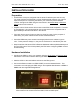
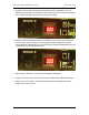
Table Of Contents
- INTRODUCTION
- HOW TO USE THIS MANUAL
- INSTALLATION CHECKLIST
- INSTALLATION GUIDE
- Preparation
- Hardware Installation
- Serial Setup – Access The PDU Using The Serial Connection
- Step 1: Download the PDU Serial Access Program
- Step 2: Connect the Computer to the PDU
- Step 3: The Main Menu – Navigating The Serial Access Program
- Step 4a: The Configure Menu – Configuring The PDU For SEMA Or SNMP
- Step 4b: The Web Menu – Configuring The PDU For Web Browser Access
- Step 5: The Monitor Menu – Monitoring The PDU With A Serial Connection
- Ethernet Setup – Access The PDU Using The Ethernet Connection
- Step 1: Configuring the Browser
- Step 2: Connect the PDU to the Network
- Step 3: Logging onto the PDU
- Step 4: The Main Menu – Navigating The Web Access Program
- Step 5: The User Menu – Assign User Passwords
- Step 6: The Configure Menu – Configure The PDU For Your Network
- Step 7: The Monitor Menu – Monitoring The PDU Using A Web Browser
- TROUBLESHOOTING GUIDE
- APPENDIX

CPI PDU User Manual Rev. 10.0. June 28, 2010
4
Product Features
• Footprint: Vertical column or horizontal 1U/2U chassis, size varies with model
• Voltage: 110 – 250 Volts, varies with model
• Power Input cable: variable length, variable plug type
• 1 Circuit Breaker per circuit segment or phase group (optional on some models)
• 1 LED Current Display per circuit segment or phase group
• Vertical controlled PDU models have bi-colored LEDs near each switched
outlet/receptacle indicating state (On/Off) – state is monitored and controlled via
Serial or Ethernet connection. Controlled models may also have several
outlet/receptacles that are not monitored or controlled (always on) which are outlined
in green. Horizontal PowerWedge models do not have LEDs that indicate state.
• Ethernet (ENET) port: Ethernet accessible via SEMA or Java-capable Web Browser.
• Serial (SER) port: Serial accessible via a direct connection with a serial cable (CPI
P/N 35941-131) to a computer that has the CPI PDU Serial program installed.
• Environmental (ENV) port: Allows attachment of an accessory Temperature and
Humidity Sensor (CPI P/N 35941-132).
• Samples and displays temperature in Fahrenheit or Celsius notation and
humidity using SEMA, a Java-capable Web Browser or the PDU Serial program
• SEMA records temperature and humidity readings and can present this
information in a report.
• Ethernet/Serial access on Monitored PDUs provides options to:
• Configure the PDU’s network address (initial configuration is required)
• Display the current drawn by each circuit segment or phase group branch
• Display the temperature and humidity if the external sensor is attached
• Set/Change Log and Alarm triggers
• Log current usage and alarms*
• Ethernet/Serial access on Controlled PDUs provides options to:
• Configure the PDU’s network address (initial configuration is required)
• Display the current drawn by each circuit segment or phase group branch
• Display the temperature and humidity if the external sensor is attached
• Set/Change Log and Alarm trigger
• Log current usage and alarms*
• Power On/Off individual controlled receptacles
• Change On Delay and Reset Delay time for each controlled receptacle
• Display the current drawn by each of the controlled receptacles
• Log current usage by each of the controlled receptacles*
*
requires Ethernet access and SEMA or an application that supports SNMP