
Manual
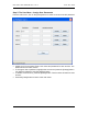
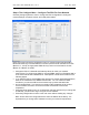


Table Of Contents
- INTRODUCTION
- HOW TO USE THIS MANUAL
- INSTALLATION CHECKLIST
- INSTALLATION GUIDE
- Preparation
- Hardware Installation
- Serial Setup – Access The PDU Using The Serial Connection
- Step 1: Download the PDU Serial Access Program
- Step 2: Connect the Computer to the PDU
- Step 3: The Main Menu – Navigating The Serial Access Program
- Step 4a: The Configure Menu – Configuring The PDU For SEMA Or SNMP
- Step 4b: The Web Menu – Configuring The PDU For Web Browser Access
- Step 5: The Monitor Menu – Monitoring The PDU With A Serial Connection
- Ethernet Setup – Access The PDU Using The Ethernet Connection
- Step 1: Configuring the Browser
- Step 2: Connect the PDU to the Network
- Step 3: Logging onto the PDU
- Step 4: The Main Menu – Navigating The Web Access Program
- Step 5: The User Menu – Assign User Passwords
- Step 6: The Configure Menu – Configure The PDU For Your Network
- Step 7: The Monitor Menu – Monitoring The PDU Using A Web Browser
- TROUBLESHOOTING GUIDE
- APPENDIX

CPI PDU User Manual Rev. 10.0. June 28, 2010
30
Max Temperature: Set the high temperature threshold (in degrees) that when
reached the PDU will send an alarm notification via SNMP trap over the network.
The range of values that should be entered is 0 through 199 degrees Fahrenheit
or -17 through 100 degrees Celsius when the Celsius box is checked. If this
variable is set to 0°F the notification is disabled.
Use Celsius checkbox: Check to provide temperature measurements in Celsius
(°C) instead of Fahrenheit (°F).
Min Humidity: Set the low humidity threshold (in %) that when reached the PDU
will send an alarm notification via SNMP trap over the network. If this variable is
set to 0 the notification is disabled. Maximum value that should be entered is
100.
Max Humidity: Set the high humidity threshold (in %) that when reached the PDU
will send an alarm notification via SNMP trap over the network. If this variable is
set to 0 the notification is disabled. Maximum value that should be entered is
100.
Name: Holds the name assigned to each of the receptacles. Maximum number of
characters must be less than 32. This field is only available on Controlled PDUs.
ON Delay: Holds the delay value (in seconds) for each of the receptacles, which
they will spend during the first power ON of the PDU. Maximum value that can be
entered is 255. This delay sequence is not applied when the circuit breakers are
reset. This field is only available on Controlled PDUs.
Reset Delay: Holds the delay value (in seconds) for each of the receptacles,
which they will spend in the OFF state before going back to the ON after
executing a reset command from the web browser. Maximum value that can be
entered is 255. This field is only available on Controlled PDUs.
Power (ON) Checkbox: Holds the current power on state for each of the
receptacles. A checked checkbox indicates that power is ON for that receptacle.
Un-checking the checkbox will turn the power OFF for that receptacle. This field
is only available on Controlled PDUs.
Maximum Current: Is the value (in Amperes) that when the branch circuit
consumption is reached the PDU will send an alarm notification via SNMP trap
over the network. If this variable is set to 0 the detection/notification is disabled.
Maximum value that can be entered is 640.00.
Maximum Socket Lock Current: Is the value (in Amperes) that when the branch
circuit consumption is reached will lock all the OFF state sockets. To turn any of
those sockets ON, the user must reduce the current consumption on the branch
or increase this value. This field is only available on Controlled PDUs.