
Manual
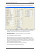
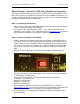
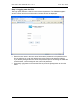
Table Of Contents
- INTRODUCTION
- HOW TO USE THIS MANUAL
- INSTALLATION CHECKLIST
- INSTALLATION GUIDE
- Preparation
- Hardware Installation
- Serial Setup – Access The PDU Using The Serial Connection
- Step 1: Download the PDU Serial Access Program
- Step 2: Connect the Computer to the PDU
- Step 3: The Main Menu – Navigating The Serial Access Program
- Step 4a: The Configure Menu – Configuring The PDU For SEMA Or SNMP
- Step 4b: The Web Menu – Configuring The PDU For Web Browser Access
- Step 5: The Monitor Menu – Monitoring The PDU With A Serial Connection
- Ethernet Setup – Access The PDU Using The Ethernet Connection
- Step 1: Configuring the Browser
- Step 2: Connect the PDU to the Network
- Step 3: Logging onto the PDU
- Step 4: The Main Menu – Navigating The Web Access Program
- Step 5: The User Menu – Assign User Passwords
- Step 6: The Configure Menu – Configure The PDU For Your Network
- Step 7: The Monitor Menu – Monitoring The PDU Using A Web Browser
- TROUBLESHOOTING GUIDE
- APPENDIX
CPI PDU User Manual Rev. 10.0. June 28, 2010
23
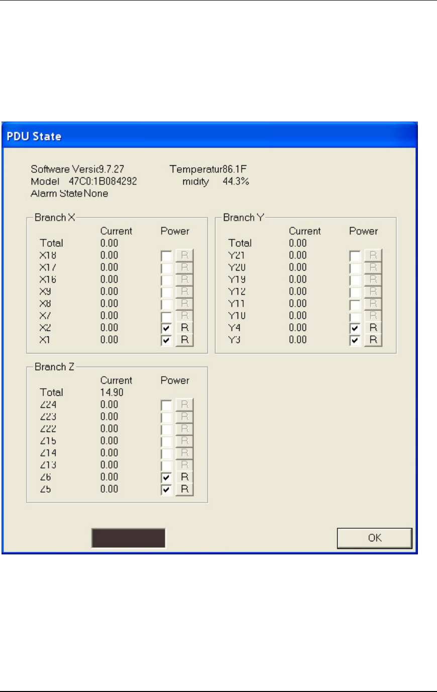
On a Controlled PDU, the PDU State screen will also include a check box to turn power
on (checked) or off (not checked) for each switched receptacle and an [R] (reset) button
to cycle power to each switched receptacle that is on.
The amount of current use by receptacle is also displayed. The PDU may include extra
receptacles that are not controlled. These receptacles are not listed under the branches,
but the total amount of current will include current use by all receptacles on the PDU.
Note: The example above is from a three-phase Controlled PDU with receptacles
grouped into three phase groups (Branch X, Y, and Z). On a single-phase PDU, the
receptacles would be grouped into one (Branch) or two circuit segments (Branch A and
B).
Click the [OK] button to exit to the main menu.