
Manual
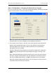
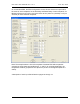
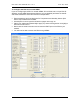
Table Of Contents
- INTRODUCTION
- HOW TO USE THIS MANUAL
- INSTALLATION CHECKLIST
- INSTALLATION GUIDE
- Preparation
- Hardware Installation
- Serial Setup – Access The PDU Using The Serial Connection
- Step 1: Download the PDU Serial Access Program
- Step 2: Connect the Computer to the PDU
- Step 3: The Main Menu – Navigating The Serial Access Program
- Step 4a: The Configure Menu – Configuring The PDU For SEMA Or SNMP
- Step 4b: The Web Menu – Configuring The PDU For Web Browser Access
- Step 5: The Monitor Menu – Monitoring The PDU With A Serial Connection
- Ethernet Setup – Access The PDU Using The Ethernet Connection
- Step 1: Configuring the Browser
- Step 2: Connect the PDU to the Network
- Step 3: Logging onto the PDU
- Step 4: The Main Menu – Navigating The Web Access Program
- Step 5: The User Menu – Assign User Passwords
- Step 6: The Configure Menu – Configure The PDU For Your Network
- Step 7: The Monitor Menu – Monitoring The PDU Using A Web Browser
- TROUBLESHOOTING GUIDE
- APPENDIX
CPI PDU User Manual Rev. 10.0. June 28, 2010
13
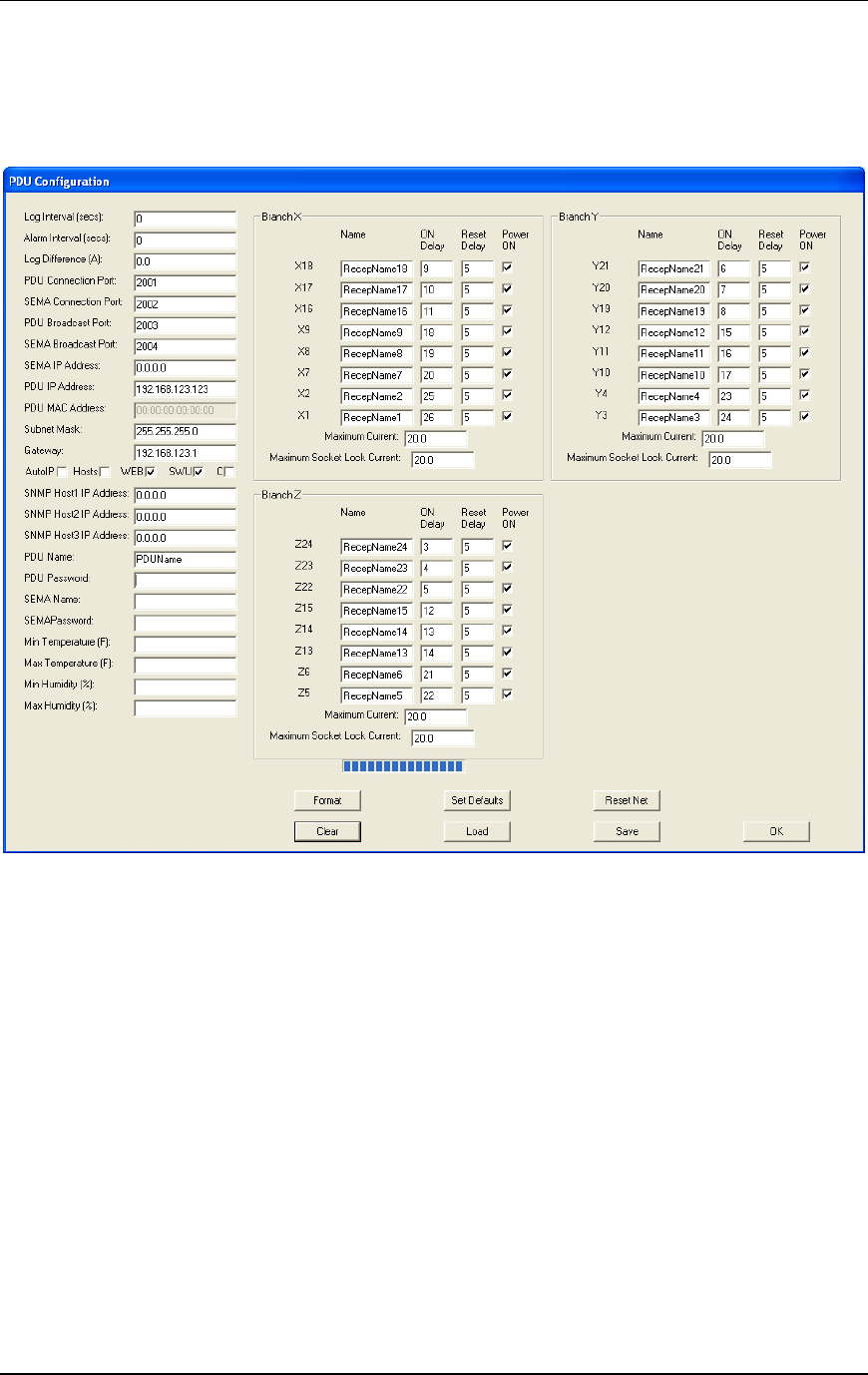
On a Controlled PDU, the PDU Configuration screen will also include an input field for
the name of each receptacle, for the ON delay and Reset Delay of each receptacle, for
Maximum Socket Lock Current, and a check box to turn power on (checked) or off (not
checked) for each switched receptacle.
Note: The example above is from a three-phase Controlled PDU with receptacles
grouped into three phase groups (Branch X, Y, and Z). On a single-phase PDU, the
receptacles would be grouped into one (Branch A) or two circuit segments (Branch A
and B).
A description of each input field is listed on pages 16 through 18.