
Manual
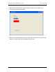
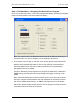
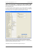
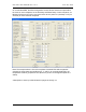
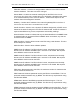
Table Of Contents
- INTRODUCTION
- HOW TO USE THIS MANUAL
- INSTALLATION CHECKLIST
- INSTALLATION GUIDE
- Preparation
- Hardware Installation
- Serial Setup – Access The PDU Using The Serial Connection
- Step 1: Download the PDU Serial Access Program
- Step 2: Connect the Computer to the PDU
- Step 3: The Main Menu – Navigating The Serial Access Program
- Step 4a: The Configure Menu – Configuring The PDU For SEMA Or SNMP
- Step 4b: The Web Menu – Configuring The PDU For Web Browser Access
- Step 5: The Monitor Menu – Monitoring The PDU With A Serial Connection
- Ethernet Setup – Access The PDU Using The Ethernet Connection
- Step 1: Configuring the Browser
- Step 2: Connect the PDU to the Network
- Step 3: Logging onto the PDU
- Step 4: The Main Menu – Navigating The Web Access Program
- Step 5: The User Menu – Assign User Passwords
- Step 6: The Configure Menu – Configure The PDU For Your Network
- Step 7: The Monitor Menu – Monitoring The PDU Using A Web Browser
- TROUBLESHOOTING GUIDE
- APPENDIX
CPI PDU User Manual Rev. 10.0. June 28, 2010
12
Step 4a: The Configure Menu – Configuring The PDU For SEMA Or SNMP
Press the [Configure] button under the Actions section of the main menu to open the
PDU Configuration screen.
On a Monitored PDU, the PDU Configuration screen will display SEMA, IP and SNMP
input fields, maximum/minimum settings for temperature and humidity, and a Maximum
Current setting for each circuit segment or phase group (Branch A and B).
Note: The example above is from a single-phase Monitored PDU with receptacles
grouped into two circuit segments (Branch A and B). On a three-phase PDU, the
receptacles would be grouped into three phase groups (Branch X, Y, and Z) and there
would be three fields to enter Maximum Current.
A description of each input field is listed on pages 16 through 18.