CPI Rack-Mount Monitored and Controlled PDU User’s Manual Version 10.0 06/2010 800-834-4969 techsupport@chatsworth.com www.chatsworth.com ©2009 Chatsworth Products, Inc. All rights reserved. CPI, CPI Passive Cooling, Saf-T-Grip, Seismic Frame, SlimFrame and MegaFrame are federally registered trademarks of Chatsworth Products, Inc. Cube-iT Plus, Evolution, OnTrac, QuadraRack, Simply Efficient and TeraFrame are trademarks of Chatsworth Products, Inc.
Chatsworth Products, Inc. 9353 Winnetka Avenue Chatsworth, CA 91311 800-834-4969 CPI Rack-Mount Monitored and Controlled PDU User Manual © 2009 Chatsworth Products, Inc. All rights reserved. The information contained in this guide is subject to change without notice. Chatsworth Products, Inc. shall not be liable for technical or editorial errors or omissions contained herein; nor is it liable for incidental or consequential damages resulting from the furnishing, performance, or use of this material.
CPI PDU User Manual Rev. 10.0. June 28, 2010 Table of Contents INTRODUCTION............................................................................................................... 2 HOW TO USE THIS MANUAL ......................................................................................... 3 GRAPHIC CONVENTIONS......................................................................................................................3 NOMENCLATURES .....................................................
CPI PDU User Manual Rev. 10.0. June 28, 2010 INTRODUCTION This document is the User’s Manual for rack-mount Monitored and Controlled PDUs by Chatsworth Products, Inc. (CPI). CPI rack-mount Monitored and Controlled PDUs provide current monitoring over the network and are accessible though a Java-compatible Web Browser or CPI’s Scalable Enterprise Management Application (SEMA) software.
CPI PDU User Manual Rev. 10.0. June 28, 2010 HOW TO USE THIS MANUAL Graphic Conventions Warning symbol. Nomenclatures ENET: Ethernet Port SER: Serial Port ENV: Environmental Port PDU: Power Distribution Unit Socket/Port/Outlet/Receptacle: PDU output port SEMA: Scalable Enterprise Management Application.
CPI PDU User Manual Rev. 10.0.
CPI PDU User Manual Rev. 10.0. June 28, 2010 INSTALLATION CHECKLIST Safety Warnings and Cautions WARNING! DO NOT open the top cover. Hazardous Voltages Present. When mounting heating issues must be taken into account. DO NOT OPEN ANY PART OF THE PDU. There are no user serviceable parts inside of the PDU. Opening or removing covers may expose you to dangerous shock hazards or other risks. Refer all servicing to qualified service personnel. • Do not spill any liquids into the chassis.
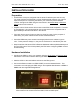
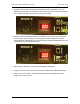
CPI PDU User Manual Rev. 10.0. June 28, 2010 Included Hardware PDU: • A vertical column (shown) or 1U/2U horizontal chassis. PDU Rack-Mount Brackets, Screws, and Nuts: • • Vertical PDUs include tool-less mounting hardware consisting of two shoulder washers and two screws; some models also include one set of brackets for attaching the PDU to a CPI cabinet or rack as indicated by the CPI part number.
CPI PDU User Manual Rev. 10.0. June 28, 2010 INSTALLATION GUIDE Preparation • All CPI PDUs come pre-configured with the same IP address (192.168.123.123). You must configure the PDU with a unique IP address that matches your network requirements prior to connecting the PDU to your network to prevent address conflicts. Configure the PDU using the instructions in the Serial Setup or Ethernet Setup sections of this manual. • Prepare a list of which servers will connect to each PDU outlet receptacle.
CPI PDU User Manual Rev. 10.0. June 28, 2010 • Optional: Connect the Temperature and Humidity Sensor (P/N 35941-132, sold separately) to the ENV port. Position the sensor where you want to take temperature and humidity readings, typically near the top of the cabinet. • Optional: Connect the Serial cable from the SER port on the PDU to the serial port on a computer. This connection is for managing the PDU using the PDU Serial Access Program [PDUSerial.exe]. The Serial Access Program [PDUSerial.
CPI PDU User Manual Rev. 10.0. June 28, 2010 Serial Setup – Access The PDU Using The Serial Connection This section explains how to access, configure and monitor (control) the PDU using a direct serial connection to a computer. You can use Serial Setup to configure the PDU so that it can be accessed with SEMA, a Web Browser or SNMP once connected to your Ethernet network.
CPI PDU User Manual Rev. 10.0. June 28, 2010 • • Start the PDU Serial Access program by double-clicking on the program icon. The following screen should display: • Select the appropriate COM Port from the drop down list and click on the [Connect] button to connect to the PDU and display the main menu.
CPI PDU User Manual Rev. 10.0. June 28, 2010 Step 3: The Main Menu – Navigating The Serial Access Program Once you connect to the PDU, a main menu with [Monitor/Status], [Configure] and [Web] buttons (Actions) similar to the screen below will display: Note: The check boxes in the Modules Present area will be different depending on the PDU model. You cannot change any of the settings in this section.
CPI PDU User Manual Rev. 10.0. June 28, 2010 Step 4a: The Configure Menu – Configuring The PDU For SEMA Or SNMP Press the [Configure] button under the Actions section of the main menu to open the PDU Configuration screen. On a Monitored PDU, the PDU Configuration screen will display SEMA, IP and SNMP input fields, maximum/minimum settings for temperature and humidity, and a Maximum Current setting for each circuit segment or phase group (Branch A and B).
CPI PDU User Manual Rev. 10.0. June 28, 2010 On a Controlled PDU, the PDU Configuration screen will also include an input field for the name of each receptacle, for the ON delay and Reset Delay of each receptacle, for Maximum Socket Lock Current, and a check box to turn power on (checked) or off (not checked) for each switched receptacle. Note: The example above is from a three-phase Controlled PDU with receptacles grouped into three phase groups (Branch X, Y, and Z).
CPI PDU User Manual Rev. 10.0. June 28, 2010 To Configure the PDU for use with SEMA If you are configuring the PDU for use with SEMA, fill in all fields, set a unique PDU IP Address, set the SNMP Host Address fields to 0.0.0.0 (disabled) and leave the AutoIP and Hosts checkboxes unchecked. See the example below. • • • • • Enter temperature and humidity limits if a Temperature and Humidity Sensor (P/N 35941-132) is attached to the PDU. A description for each input field is listed on pages 16 through 18.
CPI PDU User Manual Rev. 10.0. June 28, 2010 To Configure the PDU to send SNMP Traps If you are not using SEMA, but want the PDU to forward SNMP traps as alarms to another monitoring appliance/application when the maximum current, maximum/minimum temperature or maximum/minimum humidity is reached, fill in the SNMP Host Address fields and check the Hosts checkbox. If you need to import the PDU’s MIB files into your monitoring appliance/application, download the [PDU MIB files] from the CPI website at www.
CPI PDU User Manual Rev. 10.0. • June 28, 2010 A description of each input field on the PDU Configuration screen is listed below: Log Interval: Time interval (in seconds) that the PDU will send updated metrics to SEMA or SNMP host over network. If this variable is set to a value of less than 10 the logging is disabled. Maximum value that can be entered is 64,000. This field is only required when using the PDU with SEMA or SNMP host.
CPI PDU User Manual Rev. 10.0. June 28, 2010 PDU MAC Address: Contains the assigned MAC address for the PDU’s network interface hardware. This value cannot be changed. Subnet Mask: Contains the network masking bits for the PDU in the form of xxx.xxx.xxx.xxx, where xxx is usually 255 or 0 to designate a bit pattern that masks in the network address portion of the IP address. These values depend on the network class of the assigned IP address.
CPI PDU User Manual Rev. 10.0. June 28, 2010 Min Temperature: Set the low temperature threshold (in degrees Fahrenheit) that when reached the PDU will send an alert to SEMA or an alarm as an SNMP trap. If this variable is set to 0 the notification is disabled. Maximum value that should be entered is 199. Max Temperature: Set the high temperature threshold (in degrees Fahrenheit) that when reached the PDU will send an alert to SEMA or an alarm as an SNMP trap.
CPI PDU User Manual Rev. 10.0. • June 28, 2010 The purpose of each button on the PDU Configuration screen is described below: Format: Manufacturing initialization of the non-volatile storage for the configuration variables. This action will destroy any previous values that were saved. Set Defaults: Sets all the configuration variables to some pre-set default manufacturing values. Clear: Clears all the configuration variables. Reset Net: Makes effective the changes made to the network parameters.
CPI PDU User Manual Rev. 10.0. June 28, 2010 Step 4b: The Web Menu – Configuring The PDU For Web Browser Access Press the [Web] button under the Actions section of the main menu to open the Web Variables screen. If you are not using SEMA, but you want to access the PDU using a Java-capable Web Browser, you can change the PDU network configuration and login information from the Web Variable screen. You can also change these settings using the Ethernet Setup menus.
CPI PDU User Manual Rev. 10.0. • June 28, 2010 A description of each input field on the PDU Configuration screen is listed below: PDU Name: Name assigned to this PDU, the maximum number of characters that can be entered is less than 32. PDU IP Address: Contains the assigned IP address for the PDU in the form of xxx.xxx.xxx.xxx, where xxx is a number from 1 to 254. This field is not required if the AutoIP checkbox is checked. Subnet Mask: Contains the network masking bits for the PDU in the form of xxx.
CPI PDU User Manual Rev. 10.0. June 28, 2010 Step 5: The Monitor Menu – Monitoring The PDU With A Serial Connection To monitor the PDU using the serial connection, press the [Monitor] button under the Actions section of the main menu. On a Monitored PDU, the PDU State screen will display the Software Version, Model (MAC address), Alarm State, Temperature, Humidity, and Total Current used by each branch (circuit segment or phase group) on the PDU.
CPI PDU User Manual Rev. 10.0. June 28, 2010 On a Controlled PDU, the PDU State screen will also include a check box to turn power on (checked) or off (not checked) for each switched receptacle and an [R] (reset) button to cycle power to each switched receptacle that is on. The amount of current use by receptacle is also displayed. The PDU may include extra receptacles that are not controlled.
CPI PDU User Manual Rev. 10.0. June 28, 2010 Ethernet Setup – Access The PDU Using The Ethernet Connection This section explains how to access, configure, and monitor (control) the PDU using an Ethernet connection and a networked computer with a Java-capable Web Browser. You can also use Ethernet Setup to configure the PDU so that it can be accessed with SEMA or SNMP with a different application/appliance.
CPI PDU User Manual Rev. 10.0. June 28, 2010 Step 3: Logging onto the PDU The login panel will have a field for user name and password. The PDUWeb applet’s version number and the Java VM version number will also be displayed. • • Enter the user name in the user name field and the password in the password field. For the initial log on, enter the default user name (admin) and password (admin).
CPI PDU User Manual Rev. 10.0. June 28, 2010 Step 4: The Main Menu – Navigating The Web Access Program Once logged in, you will see four buttons: [Status], [Configure], [Users] and [Logout]. • • • • Click the [Status] button to view current, temperature and humidity measurements and to control receptacles on Controlled PDUs. See page 31 for details. Click the [Configuration] button to change IP settings, set current, temperature and alarm limits and setup alarms (SNMP traps).
CPI PDU User Manual Rev. 10.0. June 28, 2010 Step 5: The User Menu – Assign User Passwords From the main menu, click on the [Users] button to create a user account with password. • • • • Create up to four accounts. Enter a user name and password for each account. The default account is admin, admin. To change a user or password, highlight the account and press the [Change] button. You will be prompted to enter the password twice. To delete a user account, press the [Delete] button.
CPI PDU User Manual Rev. 10.0. June 28, 2010 Step 6: The Configure Menu – Configure The PDU For Your Network Click the [Configure] button to view or change the PDU configuration including the network settings, receptacle names, and initial power states. Note: This screen shows the configuration menu for a three-phase Controlled PDU. Monitored PDUs only have the Maximum Current input field under the Branch Circuits (Banch X, Y, and Z).
CPI PDU User Manual Rev. 10.0. • June 28, 2010 Descriptions of the fields are listed below. PDU MAC: Contains the assigned MAC address for the PDU’s network interface hardware. This value cannot be changed. PDU IP: Contains the assigned IP address for the PDU in the form of xxx.xxx.xxx.xxx, where xxx is a number from 1 to 254. The factory-assigned IP address is 192.168.123.123. Netmask: Contains the network masking bits (sub-net mask) for the PDU in the form of xxx.xxx.xxx.
CPI PDU User Manual Rev. 10.0. June 28, 2010 Max Temperature: Set the high temperature threshold (in degrees) that when reached the PDU will send an alarm notification via SNMP trap over the network. The range of values that should be entered is 0 through 199 degrees Fahrenheit or -17 through 100 degrees Celsius when the Celsius box is checked. If this variable is set to 0°F the notification is disabled.
CPI PDU User Manual Rev. 10.0. June 28, 2010 Step 7: The Monitor Menu – Monitoring The PDU Using A Web Browser Click the [Status] button to view current PDU conditions. The Status Dialog box will display the PDU’s MAC address, IP address, software version, temperature and humidity (if a temperature and humidity sensor is attached to the PDU), alarm state, consumption in Amperes and the status of each receptacle (on/off) on Controlled PDUs.
CPI PDU User Manual Rev. 10.0. June 28, 2010 TROUBLESHOOTING GUIDE For references of SEMA, refer to SEMA User Manual No display Check power at the source. Unplug the PDU input cable from the source and inspect the cable to make sure there are no cuts or visible damage. Inspect the input plug to make sure there are no damages to the pins. If problem persists, the PDU unit must be replaced. Display shows -1.8.8.8 Cycle power to the entire PDU. If problem persists, the PDU unit must be replaced.
CPI PDU User Manual Rev. 10.0. June 28, 2010 Verify the port integrity of the network switch/hub/router. Verify via serial port that the network configurations for the PDU are set properly. If the Ethernet communication problem persists after power cycling it, replace the PDU unit. No SEMA Connection Check the integrity of the Ethernet connection. Use SEMA server’s Device Finder application and check that it is detected with proper Hardware and IP addresses.
CPI PDU User Manual Rev. 10.0. June 28, 2010 APPENDIX Factory Default Setting Configuration variables for the PDU: Log Interval = 0 Alarm Interval = 0 Log Difference = 0 PDU Connection Port = 2001 SEMA Connection Port = 2002 PDU Broadcast Port = 2003 SEMA Broadcast Port = 2004 SEMA IP Address = 0.0.0.0 PDU IP Address = 192.168.123.123 PDU MAC Address = 0:0:0:0:0:0 Subnet Mask = 255.255.255.0 Gateway = 192.168.123.
CPI PDU User Manual Rev. 10.0. June 28, 2010 Regulatory Information Managed PDU product is compliant with the following standards and specifications: European Union: Directive No.
CPI PDU User Manual Rev. 10.0. June 28, 2010 Specifications Dimensions: Varies by model. Weights: Varies by model. Altitude: • Operating: 0 to 10,000 ft (0 to 3048 m) • Non-operating: 0 to 30,000 ft (0 to 9144 m). Audible Noise: Less than 60 db LpA (Sound pressure level at bystander position) The above noise level is not for office environment. It is for dedicated Datacenter environment. Heat Dissipation: 90 BTU/hr maximum. Shock and Vibration: • Operating: 5 to 500 Hz, 0.5 g (0.