CT4000 Family ChargePoint® Networked Charging Station Installation Guide ChargePoint, Inc. 1692 Dell Ave. Campbell, CA 95008-6901 USA US toll free: +1-877-370-3802 www.chargepoint.com Document P/N: 75-001084-01 Rev.
SAVE THESE IMPORTANT SAFETY INSTRUCTIONS This manual contains important instructions that must be followed during installation of a ChargePoint® Networked Charging Station. Grounding instructions The ChargePoint® Charging Station must be connected to a grounded, metal, permanent wiring system; or an equipment-grounding conductor is to be run with circuit conductors and connected to the equipment grounding terminal or lead on the Electric Vehicle Supply Equipment (EVSE).
Contents 1 Introduction Summary of Shipping Boxes. . . . . . . . . . . . . . . . . . . . . . . . . . . . . . . . . . . . . . . . . . . 1-1 Installation Sequence. . . . . . . . . . . . . . . . . . . . . . . . . . . . . . . . . . . . . . . . . . . . . . . . . 1-2 Before Installing. . . . . . . . . . . . . . . . . . . . . . . . . . . . . . . . . . . . . . . . . . . . . . . . . . . . . . 1-2 Specifications . . . . . . . . . . . . . . . . . . . . . . . . . . . . . . . . . . . . . . . . . . . . . . . . . . . .
Installing the Head and Top Cap Before You Start . . . . . . . . . . . . . . . . . . . . . . . . . . . . . . . . . . . . . . . . . . . . . . . . . . . . . 4-1 Overview of Steps. . . . . . . . . . . . . . . . . . . . . . . . . . . . . . . . . . . . . . . . . . . . . . . . . . . . 4-1 Step 1: Check Boxes for Correct Contents. . . . . . . . . . . . . . . . . . . . . . . . . . . . . . . 4-2 Step 2: Prepare Head Assembly for Mounting. . . . . . . . . . . . . . . . . . . . . . . . . . .
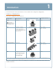
1 Introduction This document provides step-by-step instructions on how to install a CT4000 ChargePoint® Charging Station. Summary of Shipping Boxes Each CT4000 charging station ships in four boxes: Assembly name... Label on box says.... Top Cap CT40XX-CAP* High level overview of box contents... For Installation Instructions, see...
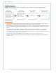
ChargePoint® Charging Stations Installation Sequence Regardless of the specific type of CT4000 charging station you are installing, and the options included, the high level installation sequence is the same: PREPARE THE INSTALLATION SITE Ensure the wiring, circuit protection, and metering is in place. Read the remainder of Chapter 1. If installing a bollard mount, also read Appendix A.
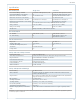
Introduction Specifications Electrical Input Single Port Dual Port AC Power Input Rating - Standard 208/240VAC 60Hz single phase @ 32A 208/240VAC 60Hz single phase @ 32A x 2 AC Power Input Rating - Power Sharing n/a 208/240 VAC 60Hz single phase @ 32A Input Power Connections - Standard One 40A branch circuit. Two independent 40A branch circuits.
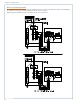
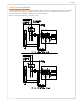
ChargePoint® Charging Stations Dual Circuit Wiring Diagram The following illustration describes the wiring for installing a CT4000 on a dual circuit. Wiring for a single circuit installation is described on the next page. Grounding requirements are described on page 1-6. NOTE: Requires two dedicated circuits, each with its own two pole 40 A breaker.
Introduction Shared Power Wiring Diagram The following illustration describes the wiring for installing a dual port CT4000 on a shared single circuit. For this installation, you will need the power sharing kit to allow both ports to share a two pole 40A circuit breaker. Wiring connections are provided in Appendix C. Grounding requirements are described on page 1-6. Wiring for a dual circuit installation, see the previous page.
ChargePoint® Charging Stations Grounding Requirements The voltage of either line, relative to ground, must not fall below 80 volts or a Floating Line Connection error occurs (see page 6-3). Because the voltage of either line relative to ground must not be allowed to fluctuate, use only centergrounded systems. Neutral is not used to power the station but must be properly connected to ground, at the panel or transformer, to provide the necessary voltage reference relative to ground.
Installing a Bollard Mount 2 Before You Start Before installing a bollard mount, prepare the installation site as described in Appendix A.
ChargePoint® Charging Stations Step 1: Check Boxes for Correct Contents The bollard mount ships in two boxes as described below.
Installing a Bollard Mount Step 2: Prepare Pole/Base Plate for Mounting • Use a 3/8” socket wrench to loosen (but not remove) the two screws holding the pole inside the bollard. • Remove the pole/base plate assembly from the main body by pulling it out from the bottom. • Remove and discard the cardboard shipping spacer.
ChargePoint® Charging Stations Step 3: Mount Pole/Base Plate Prepare the installation site as described in Appendix A, then mount the pole/base plate assembly as follows: • Pull wires through conduit. • Place the pole/base plate assembly over the conduit, ensuring the long curved edge of the base plate is located where you want the front of the charging station located. • Adjust the lower nuts as necessary to ensure the mounting pole is level.
Installing a Bollard Mount Step 4: Install Main Body To install the main body: • Align the notches on the rubber bumper with the front mounting nuts, then slide it all the way down the pole until it is flush with the base plate. This prevents any rocking motion between the main body and the base plate. • Slide the body over the mounting pole. • Re-tighten the screws you loosened in Step 2 to approximately 80 in-lbs using a 3/8” socket wrench.
ChargePoint® Charging Stations Step 5: Prepare Retractor for Mounting To prepare the retractor for mounting: • Discard shipping screws Position the retractor packaging so that the bottom of the retractor is near the base of the bollard. IMPORTANT: Do not unwrap the cords. • Remove and discard the two shipping screws from the front face of the retractor. Top NOTE: When you remove the shipping screws, the retractor’s counterweights are free to move in either direction.
Installing a Bollard Mount Step 6: Install Retractor To install the retractor: • Insert the black cap into the space at the top of the main body, between the main body and the retractor, as shown. • With a Phillips screwdriver and at least one of the four ¼” - 20 x 1 ¼” screws in hand, position the retractor against the back of the main body. Place the slot at the bottom of the retractor over the knob at the bottom of the main body, as shown.
ChargePoint® Charging Stations Step 7: Connect Wiring IMPORTANT: To power a dual-port station using a single 40A circuit, use the Power Sharing Kit (CT4020‑PSHARE) provided in the shipping box with the main body. Instead of following the instructions below, see Appendix C. You must also manually configure the station for power sharing, as described in Appendix C. If you are not installing a power sharing kit, connect the wiring as follows: • Strip wires ½” (13 mm).
Installing a Bollard Mount Step 8: Check Voltages • Turn power ON. • Using a solenoid type voltage tester, check that the voltages at the charging station’s terminal block are as follows: Measure Between Volts L1 and L2 208/240 GND and L1 120 GND and L2 120 If the voltages are not as expected, ensure that the wiring has been properly connected as describing on the previous page. For detailed wiring diagrams and grounding requirements, see pages 1-4 to 1-6.
ChargePoint® Charging Stations You have now finished installing the bollard mount and are ready to install the head assembly and top cap. See Chapter 4.
Installing a Wall Mount 3 Before You Start You need the following: • Drill and Tap for appropriate wall attachment hardware • Attachment hardware, such as 3/8” (9.5 mm) x 3” (76 mm) lag bolts if mounting to a wood wall • Ratchet and 9/16” deep socket • #2 Phillips screwdriver • Tape measure • Bubble level • Marker • Wire stripper • Multimeter Overview of Steps Installing the wall mount involves a few simple steps, summarized below and detailed in the remainder of this chapter: 1.
ChargePoint® Charging Stations Step 1: Check Boxes for Correct Contents The wall mount ships in two boxes as described below. Main Body and Mounting Kit • Main body, pre-assembled (1) • Mounting brackets with pre-installed screws and flange bolts (2 sets) NOTE: The packing box for the brackets serves as a template for drilling mounting holes. Do not discard packaging until you’ve completed Step 2.
Installing a Wall Mount Step 2: Drill Holes in Wall • The packing box for the brackets is used as a template for drilling the wall holes. Tear the packing box along the perforation to allow it to lay flat. • Place the template against the wall. As described on the package insert, align the top where indicated, 49” above the floor or ground. Ensure that the template is level and the side of the packaging insert is plumb. Mark the four mounting holes.
ChargePoint® Charging Stations Step 3: Mount Rear Brackets to Wall Mount each bracket to the wall using screws appropriate for the type of wall material. Partially insert the 1/4” - 20 screws into the rear brackets. Do not fully insert these screws—leave about 3/4” protruding.
Installing a Wall Mount Step 4: Prepare Retractor for Mounting To prepare the retractor for mounting: • Discard shipping screws Position the retractor packaging so that the bottom of the retractor is near the bottom of the wall. IMPORTANT: Do not unwrap the cords. • Remove and discard the two shipping screws from the front face of the retractor. Top NOTE: When you remove the shipping screws, the retractor’s counterweights are free to move in either direction.
ChargePoint® Charging Stations Step 5: Mount Retractor To mount the retractor assembly: • Place the two front brackets where you can easily reach them. • Tilt the retractor up against the rear brackets, with the front of the retractor facing towards you, as shown (mount holes visible). NOTE: The bottom of the retractor should rest on the ground. 3-6 • Place the top front bracket over the two corresponding screws protruding from the top rear bracket.
Installing a Wall Mount Step 6: Install Conduit As shown, the base of the main body has two conduit knockouts: 1” and ¾”. Using a flat screwdriver, remove the knockout that suits your installation needs. 1” knockout 3/4” knockout Install and seal conduit. Follow local codes.
ChargePoint® Charging Stations Step 7: Install Main Mody 3-8 • Expose the pre-drilled hole located below the terminal block. To do so, push the tab on the terminal block to release the cover plate, then slide the cover plate upwards: • Position the main body so that the top hole aligns with the top retractor bracket. • Insert a 3/8 - 16 x 3/4” flange bolt into the top hole and finger tighten. • Insert the other flange bolt into the lower mounting hole. • Tighten both flange bolts to 150 in-lbs.
Installing a Wall Mount Step 8: Connect Wiring IMPORTANT: To power a dual-port station using a single 40A circuit, use the Power Sharing Kit (CT4020‑PSHARE) provided in the shipping box with the main body. Instead of following the instructions below, see Appendix C. You must also manually configure the station for power sharing, as described in Appendix C. If you are not installing a power sharing kit, connect the wiring as follows: • Strip wires ½” (13 mm).
ChargePoint® Charging Stations Step 9: Check Voltages • Turn power ON. • Using a solenoid type voltage tester, check that the voltages at the charging station’s terminal block are as follows: Measure Between Volts L1 and L2 208/240 GND and L1 120 GND and L2 120 If the voltages are not as expected, ensure that the wiring has been properly connected as describing on the previous page. For detailed wiring diagrams and grounding requirements, see pages 1-4 to 1-6.
Installing a Wall Mount You have now finished installing the wall mount and are ready to install the head assembly and top cap. See Chapter 4.
Installing the Head and Top Cap 4 Before You Start Before installing the head and top cap, you must complete the installation of the main body and its cable management system as described in a previous chapter. You need the following: • Wire cutter • #2 Phillips screwdriver Overview of Steps Installing the head and top cap involves a few simple step, summarized below and detailed in the remainder of this chapter: 1. Check Boxes for Correct Contents (page 4-2) 2.
ChargePoint® Charging Stations Step 1: Check Boxes for Correct Contents Top cap The station’s top cap ships in a box containing: • Top cap (1) • Phillips screws (2) • CT4000 Installation Guide (this document) As illustrated below, the shape of the top cap depends on whether you are installing a bollard or a wall mount. The bollard mount’s top cap is more rounded, whereas the wall mount’s back is flatter. If installing both models, pay particular attention to the top cap’s shape.
Installing the Head and Top Cap Step 1 cont’d: Check Boxes for Correct Contents Head assembly The station’s head assembly ships in a box containing: • Head assembly • Rubber plugs (4) - two of these are spares. • T25 Allen wrench (attached with a security tag on the side of the head assembly) • Spare activation label (a duplicate label is attached to the head assembly) IMPORTANT: Keep the spare activation label for future reference.
ChargePoint® Charging Stations Step 2: Prepare Head Assembly for Mounting • To prepare the head assembly for mounting, open the box and stand the head upright on its foam packaging, as shown. • If you are installing a gateway station, install the Network Enablement Kit: a) Remove the SIM card from its carrier by pushing it firmly. a) Lift the rubber flap located on the right hand side of the head assembly, as shown. b) Insert the notched edge of the SIM card into the slot, with the notch facing upward.
Installing the Head and Top Cap Step 2 cont’d: Prepare Head Assembly for Mounting • Install the top cap a) Place the top cap over the head assembly as shown, ensuring correct alignment. b) Using a Phillips screwdriver, secure the top cap to the head assembly by inserting the two supplied screws into the back of the top cap and tightening to 20 in-lbs.
ChargePoint® Charging Stations Step 3: Slide Head Assembly Into Body Slide the head assembly into the main body until it is stopped by the head assembly’s security tag. IMPORTANT: Do not insert the charging connectors into the holsters until after you’ve powered up the station. Doing so causes the holsters to permanently lock.
Installing the Head and Top Cap Step 4: Connect Head Assembly Pull to remove the yellow strap from the blue connector. Connect the blue connector to the terminal block, ensuring it “clicks” into place. The blue connector “clicks” into place on the terminal block Push the cover down over the terminal block.
ChargePoint® Charging Stations Step 5: Verify the Station Operates Correctly Before securing the head assembly, follow these steps to verify that the station is fully operational. IMPORTANT: if the station is not operating as described below, see “Chapter 6, Troubleshooting” to resolve the error before continuing. 1. When the station is powered on, you should see: • The instructional video, and no error messages. • The status icon for each port displaying a green check mark.
Installing the Head and Top Cap Step 5 cont’d: Verify Station Operates Correctly 3. Use the ChargePoint card attached to the front cover of this Installation Guide to authorize a charging session. Make sure that both plug holsters unlock and that the station displays instructions on how to plug into the vehicle. NOTE: The ChargePoint card supplied on the front cover can authorize up to ten charging sessions.
ChargePoint® Charging Stations Step 6: Install Cable Clamps IMPORTANT: Do not unwrap the ropes until they are securely attached to the charging cable. To install the cable clamps: • Locate the bead at the end of the retractor rope. • Uncoil the charging cable by removing the plastic wrap, then gently extending it all the way out, away from the station. Rotate the plug as necessary to remove any twists or kinks. Locate the tape that marks the position where the clamp attaches to the cable.
Installing the Head and Top Cap Step 7: Secure Head Assembly To secure the head assembly: • Remove the T-25 L-wrench by rotating it to the right until the security tag breaks. Lift the head assembly slightly and remove the L-wrench. • Lower the head assembly. Ensure the head assembly is fully seated and that no gap exists between the bottom of the head assembly and the main body. The head assembly fits tightly and may require extra downward force to ensure it is fully seated.
Preparing the Station for Activation on ChargePoint 5 Before You Start Before leaving the installation site, you must prepare the station for activation. You need the following: • a laptop or tablet computer • installer user name and password for www.chargepoint.com Overview of Steps Preparing the station for activation on ChargePoint involves a few simple steps, summarized below and detailed in the remainder of this chapter: 1. Pinpoint the Station (page 5-2) 2.
ChargePoint® Charging Stations Step 1: Pinpoint the Station Follow these steps to pinpoint the station on ChargePoint. 1. Log in to ChargePoint; then, on the Manage Stations tab, click Pinpoint New Station. Manage Stations Pinpoint New Station 2. Enter the station’s MAC Address and activation password, then click Verify. NOTE: The station’s MAC Address and activation password is printed on a label that has been taped to the front of the head assembly.
Preparing the Station for Activation on ChargePoint Step 1 cont’d: Pinpoint the Station 3. Enter the station’s physical location. a) In the search field above the map, enter the station’s physical address, then click the magnifying glass. You can enter a full or partial address—you will pinpoint the exact location of the charging station in the next step. Enter the address, then click the magnifying glass b) Change to Satellite View and drag the pinpoint to the parking spot where the station is located.
ChargePoint® Charging Stations THIS PAGE INTENTIONALLY LEFT BLANK 5-4
Preparing the Station for Activation on ChargePoint Step 2: Document the Radio Groups For each radio group, attach spare activation labels below to document how stations are organized. After completing the next step on the reverse side, tear out this page and give it to the person responsible for activating the station. If installing multiple radio groups, use one page for each radio group (this page is included in all CT4000 Installation Guides).
ChargePoint® Charging Stations Step 3: Complete the Post-Installation Checklist Before leaving the installation site, complete this checklist for each radio group. Then tear out this page and give it to the person responsible for activating the station. If installing multiple radio groups, use one page for each radio group (this page is included in all CT4000 Installation Guides). þ Check each box below to confirm that the task has been completed for all stations within the radio group.
6 Troubleshooting Check the Station’s Display The CT4000’s display, and its associated error LEDs, alert you of several types of errors. For some errors, this top banner displays an error message instead of station information Under normal conditions, the station displays the instructional video In some cases, a static error message fills the entire display The status icon for each port should display a green check mark.
ChargePoint® Charging Stations Description of Station Codes Code Symptom Possible cause(s) Recommended Action(s) In most cases, a driver can resolve the following station codes that begin with the digit “1”: 101Over Current Detection During charging, the vehicle attempted to draw more power than allowed. The station stops delivering power to the vehicle. Can indicate faulty wiring in the vehicle. End the session by inserting the station’s plug back into its holster, then restart the session.
Troubleshooting Code Symptom Possible cause(s) Recommended Action(s) 205-UNS Before activation: The banner between the port icons displays “NETWORK SIGNAL NOT DETECTED.” After activation: All you will see is the code listed on Help > Station Codes. Unknown Network Signal - The gateway station is unable to establish a network connection on AT&T/ Verizon (US) or Rogers (Canada). Ensure the station is receiving an adequate signal strength from the cellular network.
ChargePoint® Charging Stations Code Symptom Possible cause(s) Recommended Action(s) ChargePoint Support may need to resolve the following station codes that begin with the digit “3”: 301-BA Breakaway Fault - The cable has been removed from the station or is damaged. The station is not operational. Call ChargePoint Customer Support at 1-877-850-4562 to arrange to have the station replaced. 302-GST GFCI Self Test Failed - The station detected a ground fault during power up and is not operational.
Troubleshooting Charging Cable Doesn’t Move Freely If the charging cable does not extend or retract fully and smoothly, it is likely that it’s rope has come off the pulley and you must re-position it. You will need: T25 L-wrench Follow these steps: 1. Using the T25 L-wrench, loosen the set screws on each side of the retractor below the top cap. 2. Each rope is attached to a weight that sits on a shelf. Pull the weight shelf up by pulling the rope located in the middle of the top cap.
ChargePoint® Charging Stations 4. Inspect the rope to ensure it is properly aligned onto the pulley. 5. Carefully lower the weight back into the retractor. 6. Rotate the top cap back into position and re-tighten the set screws to about 10 in-lbs.
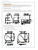
Preparing the Installation Site for a Bollard Mount A Before You Start The ChargePoint® Charging Station’s bollard mount can be installed either: • into the ground • onto an existing concrete surface (on an intermediate floor only) This appendix provides basic guidelines for preparing the installation site in both scenarios. IMPORTANT: Always check local codes to ensure compliance.
ChargePoint® Charging Stations Install J-Bolts and conduit into concrete as illustrated. To ensure correct alignment, use the template stapled into the center fold of this document (illustrated below). IMPORTANT: • The concrete block must measure at least 24” (61 cm) on all sides. Check local codes to ensure compliance. • The J-Bolts threads must extend at least 2 ½” (6.4 cm) above the concrete and 9” (23 cm) below the concrete. • The conduit must extend 12” to 24” (30 to 61 cm) above the concrete.
Installing Into Existing Concrete IMPORTANT! Follow instructions exactly as described to ensure rated performance. Ensure compliance with all applicable local and national electrical and building codes. You will need: • Three bolts at least 5/8” in diameter (length will vary depending on thickness of floor but must extend at least 2 ½” above the concrete). Each bolt must be capable of supporting a minimum of 8,000 pounds (such as a 5/8” F1554 Grade 55).
B Removing or Replacing the EV Charging Sign The method used to remove and/or replace the EV Charging Sign differs depending on whether the station has been installed. Both methods are described in this appendix. To ensure a proper fit, a replacement sign must have the following characteristics, at a minimum: • Material - Vinyl with a maximum thickness of .03” • Dimensions - Exactly 4.00” (102 mm) wide and up to 20.25” (514 mm) high A detailed sign specification is available at www.chargepoint.
ChargePoint® Charging Stations After Station Installation To remove the sign after the station has been installed: 1. Use a T25 L-wrench to loosen the set screw on each side of the top cap, as shown. 2. Pull the top assembly up and move it towards the back of the retractor. 3. Slide the existing sign out of the grooves. To install a new sign: 1. Slide the replacement sign into the grooves by bending is slightly. See the previous page for sign specifications. 2. Re-install the top assembly.
CT4000 Power Sharing Instructions C A CT402X provides 30A of charging to each port when connected to two 40A circuits, or it can be configured to allow both ports to share one 40A circuit. To allow both ports to be powered by a single 40A circuit, you must complete the steps provided this appendix. You will need the supplied power sharing kit (CT4020-PSHARE), located in the shipping box with the station’s main body.
ChargePoint® Charging Stations Step 1: Install the Jumpers WARNING: Disconnect power before you begin. • Push the black tab on the terminal block to release the terminal block cover, then slide the cover up until it locks into the raised position: • Insert the jumpers into the slots located near the upper edge of the terminal block. Using a large flat blade screwdriver, push firmly on each jumper until you feel it lock into place. IMPORTANT: Ensure both jumpers are fully seated.
Step 2: Connect the Wiring • Strip wires ½” (13 mm). 1/2” (13 mm) • • Lift the white lever on the terminal block that corresponds with the ground connection (center), insert the ground wire, then push the lever down until it clicks into its fully closed position. LEFT L1 RIGHT L1 GND LEFT L2 RIGHT L2 Lift the white levers on the terminal block that corresponds with the RIGHT port’s L1 and L2 connections.
ChargePoint® Charging Stations Step 3: Apply the Electric Rating Label Apply the supplied Electrical Rating label to the left side of the terminal block cover, just above the terminal block. NOTE: Leave the cover in the raised position to facilitate connection of the head assembly. Electrical Rating label You are now ready to install the head assembly and top cap as described in Chapter 5.
Step 4: Configure the Station for Power Sharing Follow these steps to allow the station to be powered by a single circuit: 1. Display the station’s Service Menu: • If the station is not activated on ChargePoint, simultaneously press and hold the two leftmost buttons and the rightmost button for two seconds. • If the station has been activated, scan your ChargePoint Service card Simultaneously press and hold these three buttons for two seconds to display the Service Menu on an unactivated station 2.
Limited Product Warranty D This Limited Product Warranty applies to you, a customer who has purchased CHARGEPOINT’s Charging Stations and/or related products (“Products”) from CHARGEPOINT, INC., or one of its authorized distributors and not for resale.
ChargePoint® Charging Stations defect, in either its original package or packaging providing the Product with a degree of protection equivalent to that of the original packaging, to CHARGEPOINT at the address below. You agree to obtain adequate insurance to cover loss or damage to the Product during shipment. If you obtain an RMA# and return the defective Product as described above, CHARGEPOINT will pay the cost of returning the Product to CHARGEPOINT.
ADDITIONAL INFORMATION This Limited Product Warranty is valid for U.S.A. and Canada only. This Limited Product Warranty shall be governed by and construed in accordance with the laws of the State of California, U.S.A., exclusive of its conflict of laws principles. The U.N. Convention on Contracts for the International Sale of Goods shall not apply.
1692 Dell Ave. Campbell, CA 95008-6901 USA US toll free: +1-877-370-3802 www.chargepoint.