Chaparral FS1310 Fibre Channel-to-SCSI Router User’s Guide
Copyright © 2000, 2001 Chaparral Network Storage, Inc. Document Number: 07-0015-006 This document covers the FS1310. All rights reserved. No part of this publication may be reproduced without the prior written consent of: Chaparral Network Storage, Inc. 7420 E. Dry Creek Parkway Longmont, Colorado 80503 http://www.chaparralnet.com Trademarks Chaparral Network Storage, Inc. and the Chaparral logo are trademarks of Chaparral Network Storage, Inc. AHA and AIC are trademarks of Adaptec, Inc.
Canadian Compliance Statement This Class A digital apparatus meets all requirements of the Canadian Interference-Causing Equipment Regulations. Cet appareil numérique de la classe A respecte toutes les exigences du Règlement sur le matérial brouilleur du Canada EMC Documents: 89/336/EEC—European Council Directive on the Approximation of the Laws of the Member states Relating to Electromagnetic Compatibility (EMC Directive).
6 EN 61000-4-6—Electromagnetic Compatibility (EMC) - Part 4: Testing and Measurement Techniques Section 6; Immunity to Conducted Disturbances, Induced by Radio-Frequency Fields. 7 Not needed: EN 61000-4-8 8 EN 61000-4-11—Electromagnetic Compatibility (EMC) - Part 4: Testing and Measurement Techniques Section 11: Voltage Dips, Short Interruptions and Voltage Variations Immunity Test Safety We have tested to the current (latest) version of the documents, including all revisions.
iv
Contents 1 Introduction About this Guide ...............................................................................................1-1 Conventions ................................................................................................1-2 Chaparral FS1310 Router Benefits and Features ................................................................................................1-2 About Serverless Backup ............................................................................
FS1310 Rack/Desktop Model User’s Guide Changing the Scan Delay ..........................................................................3-15 Enabling and Disabling the Alarm ............................................................3-16 Restoring the Default Settings ..................................................................3-18 Rebooting the Router .......................................................................................3-19 Changing and Displaying Device Information .............
Contents C Reference Documents Standards .......................................................................................................... C-1 Books ................................................................................................................
FS1310 Rack/Desktop Model User’s Guide viii
1 Introduction The book title is a Fibre Channel (FC)-to-Small Computer System Interface (SCSI) router that enables connectivity between SCSI devices and storage area networks (SANs). The router provides Fibre Channel connection to SCSI devices allowing them to be attached to either a Fibre Channel Arbitrated Loop (FC-AL) or switched fabric. The router allows SCSI and Fibre Channel devices to communicate seamlessly by converting data to the appropriate protocol and routing it to the desired destination.
FS1310 Rack/Desktop Model User’s Guide Conventions This Guide uses several typographical conventions to help explain how to use the router. Convention Convention Bold Words in bold indicate items to select such as menu items or command buttons. Ctrl-r Keys you press simultaneously. In this example, hold down the Ctrl key and press the r key. Notes give you important information that may affect how you decide to set up your system.
Introduction ! Industry-leading data transfer (MB/sec) and transaction processing rates (IOPS) ! Automatic SCSI device discovery and SCSI-to-FC address mapping ! Retention of SCSI-to-FC addressing during device removal/addition and between power cycles ! Support for Persistent Reserve In and Persistent Reserve Out commands ! Support for Report LUNs command ! Firmware upgrades via RS-232 ! Warnings and automatic shutdown for out-of-specification temperature and voltages ! Embedded Configurati
FS1310 Rack/Desktop Model User’s Guide The EC command, as implemented in the Chaparral router, requires no administration. Administering an EC environment is most intensive on the application side. Chaparral supports the Storage Networking Industry Association Extended Copy Specification (ANSI T10/ 99-143R1). Any questions related to using a Chaparral router in an EC environment should be directed to the application provider or your reseller.
Introduction Table 1-1.
FS1310 Rack/Desktop Model User’s Guide 1-6
2 Installing the Router This chapter provides step-by-step instructions for installing the router. You must take many factors into consideration while planning the router installation. Due to the versatility of the router and the diversity of available host platforms, host bus adapters (HBAs), switches, hubs, storage devices, and applications, only general guidelines are found in this Guide. For examples of the most common configurations, see Installation Configuration Examples on page 2-4.
FS1310 Rack/Desktop Model User’s Guide 4 Visually inspect the router and notify your freight carrier immediately of any damage. 5 Record the Media Access Control (MAC) address located on the label of the router box for future reference. Figure 2-1 below shows the front and rear panels of the FS1310. Figure 2-1.
Installing the Router Installing in a Rack You can install the router in a standard 1U high, 19" rack. You can either front or rear mount the router. Parts required for this procedure (shown in Figure 2-2) ! Left and right mounting brackets (only left bracket shown) ! Four mounting screws (10-32 panheads) Figure 2-2. Mounting bracket and screws Recommended tools for this procedure: ! #2 Phillips screwdriver To install the router in a rack: 1 Determine where in the rack you want to mount the router.
FS1310 Rack/Desktop Model User’s Guide Installation Configuration Examples You can install the router in a variety of configurations to meet your needs. The examples below show the most common installation configurations. ! Simple loop with two devices on a SAN (FC-AL) Figure 2-3. Simple loop configuration example ! Single server on a SAN (FC-AL) Figure 2-4.
Installing the Router ! Multiple servers on a SAN (FC-AL) Figure 2-5. Multiple server configuration example ! SAN with fabric (FC-SW) Figure 2-6.
FS1310 Rack/Desktop Model User’s Guide ! Multiple SANs with fabric (FC-SW) Figure 2-7. SAN with fabric configuration example ! Extended copy configuration—serverless backup that performs backup operations directly from disk to tape without copying the data to the server Host Fibre Channel Disk Array Hub Fibre Channel FS1310 Write Data Tape Drive Figure 2-8.
Installing the Router Connecting the Router The router has several types of data connections: ! Fibre Channel (gigabaud interface connector [GBIC])—permitting connection to other FC devices, typically through an arbitrated loop or SAN with fabric. ! Three SCSI channels—permitting the connection of up to 15 devices on each channel. ! RS-232 serial port—for configuration and management of the router.
FS1310 Rack/Desktop Model User’s Guide You must use the proper SCSI cables on the model you purchased. For example, if you purchased the LVD model, you must use LVD-qualified SCSI cables. Symbols on the rear panel tell you which model you have. SCSI LVD/SE SCSI DIFF LVD/SE (wide, Ultra-2 SCSI), 68-pin SCSI (LVD/SE model) Ultra wide, 68-pin SCSI (HVD model) To connect devices to the SCSI channels: 1 The router must be turned off. 2 Turn off the SCSI devices you want to connect.
Installing the Router To connect to the Fibre Channel port: 1 Be sure the router is turned off. 2 Insert the GBIC into the Fibre Channel port. See Figure 2-9 on page 2-7. The GBIC is keyed and can only go in one way. Be sure that the GBIC locks into place. 3 Connect one end of the Fibre Channel cable to the GBIC. 4 Connect the other end of the Fibre Channel cable to a server’s HBA or to an arbitrated loop hub or fabric switch.
FS1310 Rack/Desktop Model User’s Guide 3 Move the E-S switch to the S position. 4 Connect the other end of the RS-232 cable (DB-9) to the COM port on the computer that will monitor and configure the router. Connecting to the Ethernet Port You use the Ethernet (10BaseT) port to configure and manage the router. You use this configuration option when you need to manage the router from a remote computer that is connected to your LAN.
Installing the Router The router recognizes all SCSI devices connected to the three SCSI channels on the FS1310, and assigns each device a unique LUN address, which will be mapped as part of a unique FC address. You can configure the router to assign itself a LUN for in-band management, server-free backup, and other uses. To make the host FC connection: 1 Connect the Fibre Channel cable to the router and the host computer, hub, or switch.
FS1310 Rack/Desktop Model User’s Guide Table 2-12.
3 Configuring the Router You can display and change a variety of settings using the Router Administrator software.
FS1310 Rack/Desktop Model User’s Guide 2 Press Ctrl-r. The initial Chaparral FC-to-SCSI Router Administrator screen displays. 3 Press Enter. The System Menu displays. You can now perform all of the functions described in this chapter. All steps in this chapter start from the System Menu. If an alarm condition has occurred, you will see a message about the problem. This message will also be stored in the event log.
Configuring the Router Accessing the Router Administrator Using the Ethernet Port You can access the Router Administrator software using the Ethernet port using Telnet. For Windows users, if you want to use Telnet, you must configure the preferences and font from the Terminal menu each time as shown below. Click Font to set the font as shown here. Windows users may want to obtain HyperTerminal Private Edition from Hilgraeve, which supports Telnet protocol and serial port protocol.
FS1310 Rack/Desktop Model User’s Guide Accessing the Router Software Using the Ethernet Port Note: If a Telnet session is active, you cannot make changes to the configuration using the RS-232 connection. You can configure a variety of settings for the Ethernet connection. For more information, see Configuring the Additional LAN Settings on page B-3.
Configuring the Router 8 Press Enter. The System Menu displays. You can now perform all of the functions described in the following chapters. All steps start from the System Menu. Accessing the Network Management System You can access the network management system software from the Router Administrator. For more information about the settings available, see Configuring the Additional LAN Settings on page B-3.
FS1310 Rack/Desktop Model User’s Guide Table 3-1. Router Administrator navigation (Continued) To Do this Return to the previous menu or screen without saving your changes Press Esc or ←. Scroll through the available choices for a setting Press the ↑ and ↓. Note: After a few seconds of inactivity, the Router Administrator software times out and returns to the System Menu.
Configuring the Router ! Change the scan delay (see page 3-15) ! Enable and disable the alarm (see page 3-16) ! Restore the default settings (see page 3-18) Selecting the Topology You should be sure that the router’s topology setting is correct for your configuration. You can set the topology to: ! LOOP—use this option for all configurations except when the router is connected to a switch F-port. See Installation Configuration Examples on page 2-4.
FS1310 Rack/Desktop Model User’s Guide 3 Select the Topology that matches your configuration and press Enter: – LOOP—use this option for all configurations except when the router is connected to a switch F-port. See Installation Configuration Examples on page 2-4. – POINT-TO-POINT—use this option only when you connect the router to a switch F-port. See Installation Configuration Examples on page 2-4. If you selected LOOP, the Loop ID screen displays.
Configuring the Router To change the Loop ID: 1 From the System Menu, select Configuration Menu and press Enter. The Configuration Menu screen displays. 2 Select Host Configuration and press Enter. The Host Configuration screen displays. 3 Select the topology you want and press Enter, or press Enter if the correct topology is already selected. The current setting is marked with an * next to it. For information about the topology selection, see Selecting the Topology on page 3-7.
FS1310 Rack/Desktop Model User’s Guide 5 Press Enter. If you want to change the router LUN, you can do so. See Changing the Router’s FC LUN on page 3-10. The system confirms that you want to make the change. 6 Select Yes and press Enter to make the changes. The system confirms that the changes are made. 7 Press Enter to return to the Configuration Menu. 8 Reboot the router. Note: If you change the topology, Loop ID, or router LUN, you must reboot the router for the change to take effect.
Configuring the Router If you selected LOOP, the Loop ID screen displays. To display the Router LUN screen, press Enter. If you want to change the Loop ID, you can do so. See Changing the Router’s Loop ID on page 3-8. If you selected POINT-TO-POINT, the Router LUN screen displays. The text inside the parentheses ( ) shows the current Router LUN setting. 4 Select the option or number you want to use and press Enter.
FS1310 Rack/Desktop Model User’s Guide Changing the SCSI ID Assigned to Each Router Channel The router assigns each of its SCSI channels one of the SCSI IDs (initiator IDs), leaving 15 SCSI IDs available for devices. You can change the SCSI ID assigned to each channel. To change the SCSI ID assigned to a router channel: 1 From the System Menu, select Configuration Menu and press Enter. The Configuration Menu screen displays. 2 Select Channel Configuration and press Enter.
Configuring the Router 4 Select the SCSI ID (Initiator ID) you want to use for this channel and press Enter. Depending the model you have, other screens may display. The system confirms that you want to make the change. 5 Select Yes and press Enter to make the changes. The system confirms that the changes are made. 6 Press Enter to return to the Configuration Menu.
FS1310 Rack/Desktop Model User’s Guide Setting the Date and Time You can set the router’s date and time. To set the router’s date: 1 From the System Menu, select Configuration Menu and press Enter. The Configuration Menu screen displays. 2 Select Set Date/Time and press Enter. The Set Date/Time screen displays. 3 Select Set Date and press Enter. The Set Date screen displays. 4 Enter the date you want and press Enter. Enter the date in the following format: MM/DD/YYYY.
Configuring the Router The Configuration Menu screen displays. 2 Select Set Date/Time and press Enter. The Set Date/Time screen displays. 3 Select Set Time and press Enter. The Set Time screen displays. 4 Enter the time you want and press Enter. Enter the time in the following format: hh:mm:ss. The system confirms that you want to make the change. 5 Select Yes and press Enter to make the changes. The system confirms that the changes are made. 6 Press Enter to return to the Configuration Menu.
FS1310 Rack/Desktop Model User’s Guide 2 Select Scan Configuration and press Enter. The Scan Configuration screen displays. 3 Select the number of seconds you want the router to wait and press Enter. You can select any number between 0 and 255. The system confirms that you want to make the changes. 4 Select Yes and press Enter to make the changes. The system confirms that the changes are made. 5 Press Enter to return to the Configuration Menu.
Configuring the Router Table 3-3 shows the temperature and voltage thresholds for each alarm and what to do to resolve the problem. Table 3-3. Alarm thresholds Alarm threshold CPU temperature Warning—5°C and 65°C Shutdown—0°C and 70°C What to do when the alarm sounds ! ! ! On-board temperature Warning—5°C and 45°C Shutdown—0°C and 50°C VCC voltage Warning—5V -3.5% and +6.5% Shutdown—5V -6.
FS1310 Rack/Desktop Model User’s Guide To enable or disable the alarm: 1 From the System Menu, select Configuration Menu and press Enter. The Configuration Menu screen displays. 2 Select Alarm and press Enter. The Alarm screen displays. The current setting is marked with an * next to it. 3 Select the option you want and press Enter. The system confirms that the changes are made. 4 Press Enter to return to the Configuration Menu.
Configuring the Router 2 Select Restore Defaults and press Enter. The Restore Defaults screen displays. The selected option is marked with an * next to it. 3 Select Yes and press Enter to make the change. The system confirms that the changes are made. 4 Press Enter to return to the Configuration Menu. Rebooting the Router You must reboot the router after you change the topology, Loop ID, or router LUN. You should also reboot the router when you connect new devices.
FS1310 Rack/Desktop Model User’s Guide Changing and Displaying Device Information You can change and display information about the devices connected to the router using the Router Administrator.
Configuring the Router 2 Select Mapping Mode press Enter. The Mapping Mode screen displays. The current setting is marked with an * next to it. 3 Select the option you want and press Enter: AUTO—lets the router assign the FC LUN to each device anytime you power up the router. FIXED—tells the router to keep the same FC LUN as currently assigned for each device. This reserves the same FC LUN for each device, even when you power down and power up the router.
FS1310 Rack/Desktop Model User’s Guide To change the device FC LUNs: 1 Set the address mode to FIXED. See Changing the Mapping Mode (AUTO or FIXED) on page 3-20. 2 From the System Menu, select Address Mapping and press Enter. The Address Mapping screen displays. 3 Select Display Address Map press Enter. The Display Address Map screen displays. 4 Select the device whose LUN you want to change and press Enter. The Change Address Map screen displays.
Configuring the Router Displaying the Devices Connected to the Router You can display a list of the SCSI devices connected to the router. Currently, the list only includes the first 15 devices on each channel. To display a list of all devices, see Displaying the FC-to-SCSI Address Map on page 3-23.
FS1310 Rack/Desktop Model User’s Guide The address map lists devices in ascending order based on the FC LUN, including the router itself if it has an FC LUN assigned to it. For additional information about address mapping, see Appendix A, Address and Device Mapping. To display the address map: 1 From the System Menu, select Address Mapping and press Enter. The Address Mapping screen displays. 2 Select Display Address Map press Enter. The Display Address Map screen displays.
Configuring the Router ! Firmware update ! Temperature warning ! Temperature failure (this leads to a shutdown of router which is logged as a shutdown) ! Voltage warning ! Voltage failure (this leads to a shutdown of router which is logged as a shutdown) You should check the log regularly. The event log stores the most recent 400 events. Events are numbered from 001 to 999. The numbering wraps back to 001 after reaching 999.
FS1310 Rack/Desktop Model User’s Guide 2 Select View Event Log and press Enter. The Event Log screen displays the last event that occurred. 3 Press ↑ to see the previous event. You can continue to view earlier events by pressing ↑. 4 Press Esc to return to the Event Log Menu. To display a full page of events: 1 From anywhere in the Router Administrator software, press Ctrl-e. The first screen of events from the event log displays. 2 Press d to page down or u to page up in the log.
Configuring the Router Displaying Hardware and Configuration Information You can display the router’s hardware and configuration information. This is where you can see what version of the firmware you have. Chaparral technical support personnel may also request this information. You can display the hardware and configuration information two ways: ! Hardware information only ! Hardware and configuration information Table 3-4 lists the configuration information that is available. Table 3-4.
FS1310 Rack/Desktop Model User’s Guide Table 3-4. Configuration information (Continued) Group Field What displays ROUTER Alarm ENABLED or DISABLED as set in the Router Administrator software. CAPI Version Version of the Configuration Application Programming Interface. FC LIB Version Version of the FC library. Field To display hardware information only: 1 From the System Menu, select Utilities Menu and press Enter. The Utilities Menu screen displays.
Configuring the Router To display hardware and configuration information: 1 From anywhere in the Router Administrator software, press Ctrl-e. The first screen of events from the event log displays. 2 Press Ctrl-e again The Hardware Information screen displays. 3 Press Ctrl-e again. The Configuration Information screen displays. 4 Press Esc to return to where you started from.
FS1310 Rack/Desktop Model User’s Guide Displaying the Router’s FC LUN You can display the router’s FC LUN and the FC LUNs of each device connected to the router. To display the router’s LUN: 1 From the System Menu, select Address Mapping and press Enter. The Address Mapping screen displays. 2 Select Display Address Map and press Enter. The Display Address Map screen displays listing the router and all devices in the order of their assigned FC LUN. In the example screen below, the router is the last item.
Configuring the Router Upgrading Firmware You can upgrade the firmware for the router and the Ethernet card in the router. Information regarding the latest release of firmware and firmware updates is available from the Chaparral Web site (www.chaparralnet.com/support). Contact Chaparral technical support for the password to access the firmware updates. Upgrading the Router’s Firmware You use the Flash Utility to download new firmware (.
FS1310 Rack/Desktop Model User’s Guide 6 While the router reboots, hold down the space bar on your keyboard. The Flash Utility screen displays. 7 Press the number on your keyboard that corresponds to the protocol you want to use to transfer the firmware upgrade file from your computer to the router. We recommend using the KERMIT protocol. The system shows that it is ready to use KERMIT. 8 Using your terminal emulator software, send the .fla file using KERMIT.
Configuring the Router Upgrading the Ethernet Card’s Firmware You can also update the firmware for the Ethernet card inside the router. The firmware is contained in a .bin file. To upgrade the Ethernet card’s firmware: 1 Call Chaparral technical support for information about downloading the firmware updates. See Chaparral Technical Support on page 4-1 2 From the computer connected to the router, access the DOS window. 3 At the DOS prompt change to the directory where you downloaded the .bin file.
FS1310 Rack/Desktop Model User’s Guide 3-34
4 Troubleshooting Resolutions to common problems you may encounter are described in the following sections. This section describes troubleshooting using the RS-232 serial port. ! Caution: Do not remove the router’s cover. The router has no userserviceable parts. Removing the cover will void the warranty. Chaparral Technical Support For assistance configuring and using your Chaparral product, contact your authorized distributor or send an e-mail to Chaparral technical support at support@chaparralnet.com.
FS1310 Rack/Desktop Model User’s Guide Table 4-1. POST diagnostic errors and solutions Diagnostic Failure Solutions Default hardware register Replace the router. Default chip set register Replace the router. Voltage/temperature 1. Check for thermal problems in the environment. 2. Check any airflow obstruction. 3. Replace the router. Local DRAM memory test Replace the router. LVDS BIST Replace the router. PCI configuration verification Replace the router.
Troubleshooting Restoring the Default Configuration Through the Flash Utility You can clear the router configuration and restore all router default settings without accessing the Router Administrator software. You may want to do this if the router is not working properly or the system hangs after the “All diagnostic tests passed” message, as shown on the following screen. To restore the default configuration: 1 After powering on the system, hold down the space bar to prevent the system from rebooting.
FS1310 Rack/Desktop Model User’s Guide 2 Select 6. Utility Menu and press Enter. The Utility Menu screen displays. 3 Select 2. Clear Configuration and press Enter. 4 The system confirms that you want to make the change. Enter Y to confirm and press Enter to clear the configurations. 5 The system confirms that the changes are made. 6 Press q to quit the Utility Menu. 7 Select 5. Run Bridge to verify the configurations have been cleared.
Troubleshooting Problem: Nothing is displayed on the terminal emulator. Solution: The probable cause of this problem is your terminal emulator software is not configured correctly. Problem: Screen is updated, but won’t respond to keystrokes. Solution: 1 Check that all the cables are connected properly. 2 Make sure the E/S switch is on S if you are trying to use the serial port. 3 Check that the correct COM port is enabled and configured.
FS1310 Rack/Desktop Model User’s Guide Router is Not Responding Problem: The router is turned on and connected, but is not working properly and its LED lights are not lit. Solution: Replace the fuse. Note: Be sure to use an F2H, 250V fuse. 1 Insert a small flat-blade screwdriver under the tab where the fuse is located and pull out the fuse and fuse box. See Figure 2-9 on page 2-7. 2 Remove the spare fuse from the box and replace the old fuse. 3 Reinstall the fuse and fuse box.
Troubleshooting Note: Event numbers restart at 000 after 999 events have been logged. 3 Use the ↑ and ↓ keys to browse through the list of events. To view a whole screen of events at once follow these steps: 1 Type Ctrl-e to switch screens until the Event Log screen appears (the text “Event Log” is located in the lower left corner of the screen). 2 Use this screen to view multiple events simultaneously. The ↑ and ↓ keys allow you to scroll. u moves the screen up a page. d moves the screen down a page.
FS1310 Rack/Desktop Model User’s Guide Voltage and Temperature Errors and Warnings Most voltage and temperature errors occur due to environmental conditions. See Table 1-1 on page 1-4 for environmental specifications. Setting Up Debug Logging The router has a debug log that you can view by pressing Ctrl-E. Pressing Ctrl-E toggles you through the event log, debug log, hardware information, and configuration information screens.
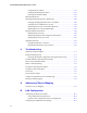
A Address and Device Mapping Devices attached to the router are discovered during power on. The router defaults to AUTO mapping mode, which automatically maps the SCSI devices at each power on. The router maps devices sequentially as it scans the channels and discovers the devices (devices are discovered by channel, lowest SCSI ID and LUN first). Devices are mapped to FC LUNs, starting from LUN 0 to LUN 63 (64 LUNs are supported, including an optional router LUN).
A-2 Bus:Target ID 0:0 0:1 0:2 . . . 3:29 ? Mapping depends on Host HBA and driver Fibre Channel FC Address 0x0000EF 0x0000E8 0x0000E4 . . . 0x000001 ? Host Computer Loop ID AL_PA 0xEF 0xE8 0xE4 . . . 0x01 ? 1 15 7 7 Figure A-1. FS1310 device address mapping Take first available (starting at 0xEF) Loop ID 0 1 2 . . .
Address and Device Mapping Loop ID to AL_PA Mapping During the Fibre Channel Arbitrated Loop (FC-AL) initialization process, a unique Arbitrated Loop Physical Address (AL_PA) value is assigned to each port on the loop. Not all of the 256 hex values are allowed as AL_PA values per FC-AL, so Loop IDs are used to represent the 125 addresses that the router can use. You can assign a Loop ID to the router. See Changing the Router’s Loop ID on page 3-8. Table A-2 shows how a Loop ID value maps to an AL_PA.
FS1310 Rack/Desktop Model User’s Guide Table A-2.
B LAN Configuration Before you can access the Router Administrator software using the Ethernet port, you must set up your router for TCP/IP. The following sections describe the router’s TCP/IP setup. A router that is part of a TCP/IP network requires three basic IP configuration elements: IP address, subnet mask, and default gateway IP address. The router’s IP address must be unique to the network in which the router resides.
FS1310 Rack/Desktop Model User’s Guide Using Address Resolution Protocol The ARP configuration method requires no IP address re-configuration of any computer on the network. The ARP command is available in various forms and sometimes with varying syntax in UNIX and Windows systems. All routers are shipped with a unique Media Access Control (MAC) hardware address (sometimes referred to as a physical address).
LAN Configuration Dynamic Host Configuration Protocol Configuration The Dynamic Host Configuration Protocol (DHCP) is a protocol designed to make IP address assignment dynamic and automatic. When a router is configured in DHCP mode, it generates a request for an IP address. The address is provided to the router and can be used from that point forward. In the dynamic address assignment mode, an IP address is leased to a DHCP-configured router.
FS1310 Rack/Desktop Model User’s Guide 3 Select Ethernet Config and press Enter. The Network Management System Console screen displays. From here you can access the LAN settings. Each screen and its settings are described briefly in the following sections. These settings are intended for use by experienced network administrators. Refer to your operating system documentation for more information about these settings.
LAN Configuration System Configuration Screen Option 1 from the Network Management System Console screen displays the System Configuration screen. Table B-1 describes the settings you can change here. Table B-1. System Configuration screen settings Option Setting Description 1 System name Name of the router as seen by other systems on the network. You can enter up to 80 characters. Default is router fxxxxx where xxxxx is the last 5 digits of the MAC address.
FS1310 Rack/Desktop Model User’s Guide TCP/IP Configuration Screen Option 2 from the Network Management System Console screen displays the TCP/IP Configuration screen. Table B-2 describes the settings you can change here. Table B-2. System Configuration screen settings Option Setting Description 1 IP Address Internet Protocol address of the router. Default is 10.0.0.1. 2 IP Mask Subnet mask. Default is 255.255.255.0. 3 Gateway Default is 0.0.0.0.
LAN Configuration SNMP Configuration Screen Option 3 from the Network Management System Console screen displays the SNMP Configuration screen. Table B-3 describes the settings you can change here. Table B-3. System Configuration screen settings Option Setting Description 1 SNMP Trap Host Host computer’s IP address that is set up to receive SNMP traps. Default is 0.0.0.0. 2 SNMP Traps Enabled? On or off toggle to enable SNMP traps. Default is No (disabled). 3 Read Community SNMP read password.
FS1310 Rack/Desktop Model User’s Guide System Information screen Option 5 from the Network Management System Console screen displays the About Network Interface screen displays. You can view this read-only screen to get information about the system. Returning to the Router Administrator Software Press Esc from the Network Management System Console screen to return to the Router Administrator software. Either the initial screen or the System menu displays.
C Reference Documents Standards X3T11/Project 755D Fibre Channel Physical and Signaling Interface (FC-PH) Specification - ANSI Standard X3.230-1994 X3T11/Project 1133D Fibre Channel Arbitrated Loop (FC-AL-2) Specifications, Rev 6.1 Draft ANSI Standard X3T11/Project 959D Fibre Channel Switch Fabric (FC-SW) – Draft ANSI Standard X3T11/Project 1162DT Fibre Channel Private Loop SCSI direct attach (FC-PLDA) – Draft ANSI Standard X3T10/Project X3.
FS1310 Rack/Desktop Model User’s Guide Document title Abbreviation SCSI-3 Fast-20 Parallel Interface Project Number [T10/1071-D] SCSI-3 Interlocked Protocol SIP [T10/856-D] SCSI-3 Serial Bus Protocol SBP [T10/992-D] Note: Working draft standards documents in this section are available from the following Web sites: http://www.t11.org/, http://www.t10.org/. The exact status, revision level, and location may change as the drafts become standards and are released.
Glossary “A” controller—In Active-Active mode, one controller is designated as the “A” controller and the other controller is designated as the “B” controller. Controller identity is determined by enclosure hardware. The controller’s identity displays continuously at the bottom of the Disk Array Administrator screens. Address—An address is a data structure or logical convention used to identify a unique entity, such as a particular process or network device.
FS1310 Rack/Desktop Model User’s Guide FC protocol for SCSI (FCP)—FCP defines an FC mapping layer (FC-4) that uses FCPH services to transmit SCSI command, data, and status information between a SCSI initiator and SCSI target. FCP enables transmission and receipt of SCSI commands, data, and status across the FC using standard FC frame and sequence formats.
Glossary Loop address—Loop address is an FC term that indicates the unique ID of a node in FC loop topology. A loop address is sometimes referred to as a Loop ID. Low voltage differential (LVD)—LVD is a method of powering SCSI cables that will be formalized in the SCSI-3 specifications. LVD uses less power than the current differential drive (HVD), is less expensive, and allows for higher speeds such as those of Ultra2 SCSI. LVD requires 3.3 volts (versus 5 volts for HVD).
FS1310 Rack/Desktop Model User’s Guide SCSI port—A SCSI port is an opening at the back of a router that provides connection between the SCSI adapter and SCSI bus. Simple Network Management Protocol (SNMP) —SNMP is the Internet standard protocol, defined in STD 15, RFC 1157, developed to manage nodes on an Internet Protocol (IP) network. Small computer system interface (SCSI) —SCSI is an industry standard for connecting peripheral devices and their controllers to an initiator.
Index 0 light 2-12 1 light 2-12 2 light 2-12 A About Network Interface screen B-8 accessing the Router Administrator software 3-1 Address Mapping screen 3-20 Address Resolution Protocol, using to resolve IP address B-2 addresses changing for devices 3-21 changing mapping mode of 3-20 displaying FC-to-SCSI address map 3-23 FC-to-SCSI mapping A-1 alarm disabling 3-16 enabling 3-16 temperature thresholds for 3-18 voltage thresholds for 3-18 Alarm screen 3-18 ARP, using to resolve IP address B-2 AUTO setting 3
FS1310 Rack/Desktop Model User’s Guide displaying 3-23 configuration information 3-27 devices 3-23 events 3-24 hardware information 3-27 E enabling, the router’s alarm 3-16 Ethernet card upgrading firmware 3-33 Ethernet port accessing the Disk Array Administrator software 3-3, B-1 connecting to 2-10 Event Log Menu 3-25 Event Log screen 3-26 event log, displaying 3-24 events, displaying 3-24 Extended Copy 1-3 F FC light 2-11 FC LUNs changing for devices 3-21 changing mapping mode 3-20 displaying for route
Index resolving using ARP B-2 resolving using DHCP B-3 Network Management System Console screen B-7, B-8 NONE setting 3-10 L P LAN, setting up to access controller software 3-3, B-1 LED lights 2-11 LED status lights 2-11 lights 2-11 Loop ID changing for router 3-8 settings for 3-8 SOFT setting 3-8 Loop ID screen 3-9 Loop ID to AL_PA mapping A-3 LOOP topology setting 3-7 LUNs changing for devices 3-21 changing for router 3-10 displaying for router 3-30 NONE setting 3-10 settings for 3-10 SOFT setting 3-
FS1310 Rack/Desktop Model User’s Guide configuring 3-1 configuring TCP/IP B-1 connecting to the Ethernet port 2-10 connecting to the FC port 2-8 connecting to the RS-232 port 2-9 connecting to the SCSI channels 2-7 default settings 2-12 disabling the alarm 3-16 disabling the termination 3-13 displaying configuration information 3-27 displaying devices connected to 3-23 displaying events 3-24 displaying hardware information 3-27 displaying its FC LUN 3-30 enabling the alarm 3-16 features 1-2 installing 2-1
Index SCSI channels changing mapping mode 3-20 connecting to 2-7 HVD 2-8 LVD 2-8 problems with 4-5 single-ended narrow 2-8 Ultra2 wide 2-8 SCSI devices changing addresses of 3-21 changing FC LUNs of 3-21 displaying 3-23 SCSI ID, changing for router 3-12 self-test, table of failures and solutions 4-2 serial port 2-9 connecting to 2-9 problems with 4-4 serverless backup 1-3 Set Date screen 3-14 Set Date/Time screen 3-14 Set Time screen 3-15 setting up the router 3-1 settings for the RS-232 port 2-9 settings
FS1310 Rack/Desktop Model User’s Guide I-6
Chaparral Network Storage, Inc. 7420 E. Dry Creek Parkway Longmont, CO 80503 © 2000, 2001 Chaparral Network Storage, Inc. All rights reserved. Chaparral and Chaparral logo are trademarks of Chaparral Network Storage, Inc. Printed in the U.S.