
Product Manual


13
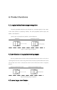
T < = TTC and L < L1
Level 2
warning
FA 02 XX XX 00 00 00 FE
FA
00
AA
BB
CC
DD
00
FA
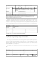
Data protocol
head
Y=0xAABB V=0xCCDD alarm level Distance =(y-
32768)/10 speed =(V-32768)/10 unit: m, step: 0.1
unit: m/s
The
reserved
The tail
No alarm
FA 00 00 00 00 00 00 FE
Level 1 warning
FA 01 XX XX XX XX 00 FE
Level 2 warning
FA 02 XX XX 00 00 00 FE
Note: For example, the data ID 0x401 received on the 485 bus: FA 01 80 66 7F CA 00 FE indicates
that the radar gives early warning, the obstacle is in front of 10.2m, the speed is -5.4m /s, and
the negative sign indicates approaching to the radar
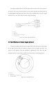
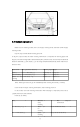
Note: This radar needs to be connected to the vehicle 485 bus to obtain the vehicle speed from the
bus. When the vehicle speed is greater than the starting speed, the radar will start to work. For the
convenience of customer testing, the starting speed of the radar is 0 by default. If the starting speed needs
to be set, the starting speed can be set with 485. The format of the set protocol is shown in the figure below:
The frame ID
0x201
The frame type
The standard frame
Baud rate
115200
8C
AA
Data protocol
head
V = 0 xaa * 0.1 km/h
For example, send: 8C BE and set the starting speed to BE 19km/h
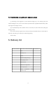
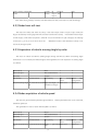
6.3.1 Radar early-warning output mode setting
The warning output mode of the radar can be set through the 485 bus. Select the 485 output mode or
IO port output mode, and the radar defaults to IO port output mode. Connect the 485 bus of the radar
with the 485 adapter, open the upper computer (or 485Test software) adapted to the 485 box, select the
device model USB485-2E-U and baud rate
Select 115200, other Settings can be set by default. The specific protocols are shown in the following
table:
The frame ID
0x201
The frame type
The
standard
frame
Baud rate
115200
Set the item
The data format
Data parsing
Set success
return
Return after
setting failure